
"Hot" for Warm Water Cooling (SC11 State of the Practice paper, LBNL-5128E)
Energy Efficient HPC Working Group / Lawrence Berkeley National Laboratory · Henry Coles, Michael Ellsworth et al.
A paper from the Energy Efficient HPC Working Group that derives, from climate data and step by step, the maximum building-supplied water temperatures for compressor-free cooling of supercomputers.
On this page
Overview
This paper is a State of the Practice paper prepared for SC11 (ACM/IEEE Supercomputing 2011) in Seattle, published by the Energy Efficient HPC Working Group and Lawrence Berkeley National Laboratory (LBNL-5128E). Its authors are Henry Coles, Michael Ellsworth and David J. Martinez. The paper offers a clear worked method for building up a supply temperature from climate data.
The method uses 99.6% design wet- and dry-bulb conditions for 15 US national-laboratory sites. Across these sites, dry bulb is at or below 37.5 C and wet bulb at or below 26.5 C for 99.6% of the year, the remaining 0.4% being about 35 hours. Component approach temperatures are stacked for cooling-tower and dry-cooler chains: cooling tower 3.8 C, dry cooler 5.5 C, plate-and-frame heat exchanger 1.7 C and CDU 2.8 C, plus pre-heat and chip-level allowances. The result feeds either air-cooled or direct-liquid-cooled IT, and the remaining margin to a reference CPU's case limit is checked.
The results are as follows. A cooling tower at 26.5 C wet bulb gives a 32 C building supply; with direct liquid cooling the CPU case reaches about 52 C, a 26 C margin to a 77.6 C limit, whereas with air cooling the margin is 14 C. A dry cooler at 37.5 C dry bulb gives a 43 C supply; the margin is 12 C with direct liquid cooling but only 3.4 C with air at the chip. The paper recommends 32 C for cooling-tower-based supply and 43 C for dry-cooler-based supply, which fed into ASHRAE's W-class liquid cooling guidelines.
In the solutions considered, about 90% or more of the heat is typically removed by liquid. The guideline parameters identified for future work include minimum and maximum supply temperature, minimum return rise, water quality, percent of heat to liquid, maximum static pressure, minimum differential pressure and rate of change of supply temperature. As a limit, this is a 2011 study based on US sites and a specific reference CPU; the method is flexible but the numbers must be recalculated for another climate and hardware.
Key points
- Design conditions across the 15 sites: dry bulb at or below 37.5 C and wet bulb at or below 26.5 C for 99.6% of the year (the remaining 0.4% is about 35 h).
- Approach temperatures assumed: cooling tower 3.8 C, dry cooler 5.5 C, plate-and-frame HX 1.7 C, CDU 2.8 C, plus pre-heat and chip-level allowances.
- Cooling tower at 26.5 C wet bulb gives 32 C building supply; direct liquid cooling puts the CPU case at about 52 C, a 26 C margin to 77.6 C; with air cooling the margin is 14 C.
- Dry cooler at 37.5 C dry bulb gives 43 C supply; margin is 12 C with direct liquid cooling but only 3.4 C with air at the chip.
- Recommendation: 32 C for cooling-tower-based and 43 C for dry-cooler-based supply, which fed into ASHRAE's W-class guidelines.
- About 90% or more of heat is typically removed by liquid in the solutions considered.
- Parameters identified for future work: min/max supply temperature, minimum return rise, water quality, percent of heat to liquid, max static pressure, min differential pressure, rate of change of supply temperature.
Using it in design
- Implement this stack-up as a design check: from the site's 99.6% design wet and dry bulb plus per-component approaches, compute the achievable chiller-less supply temperature.
- Compare the result with the IT liquid class, for example warn if a dry-cooler design is paired with air-at-chip IT needing below 43 C.
- Report the CPU case temperature margin separately for direct liquid and air cooling.
- Recalculate the figures for your own climate and hardware.
Monthly newsletter · free
Keep your reading list current
Once a month: new library sources, changes to Turkish regulations and upcoming data centre events.
SoSo CAD
Check cooling capacity alongside your design
Review zone heat loads, available capacity and the capacity balance after the largest unit is lost in SoSo CAD.
Request a demo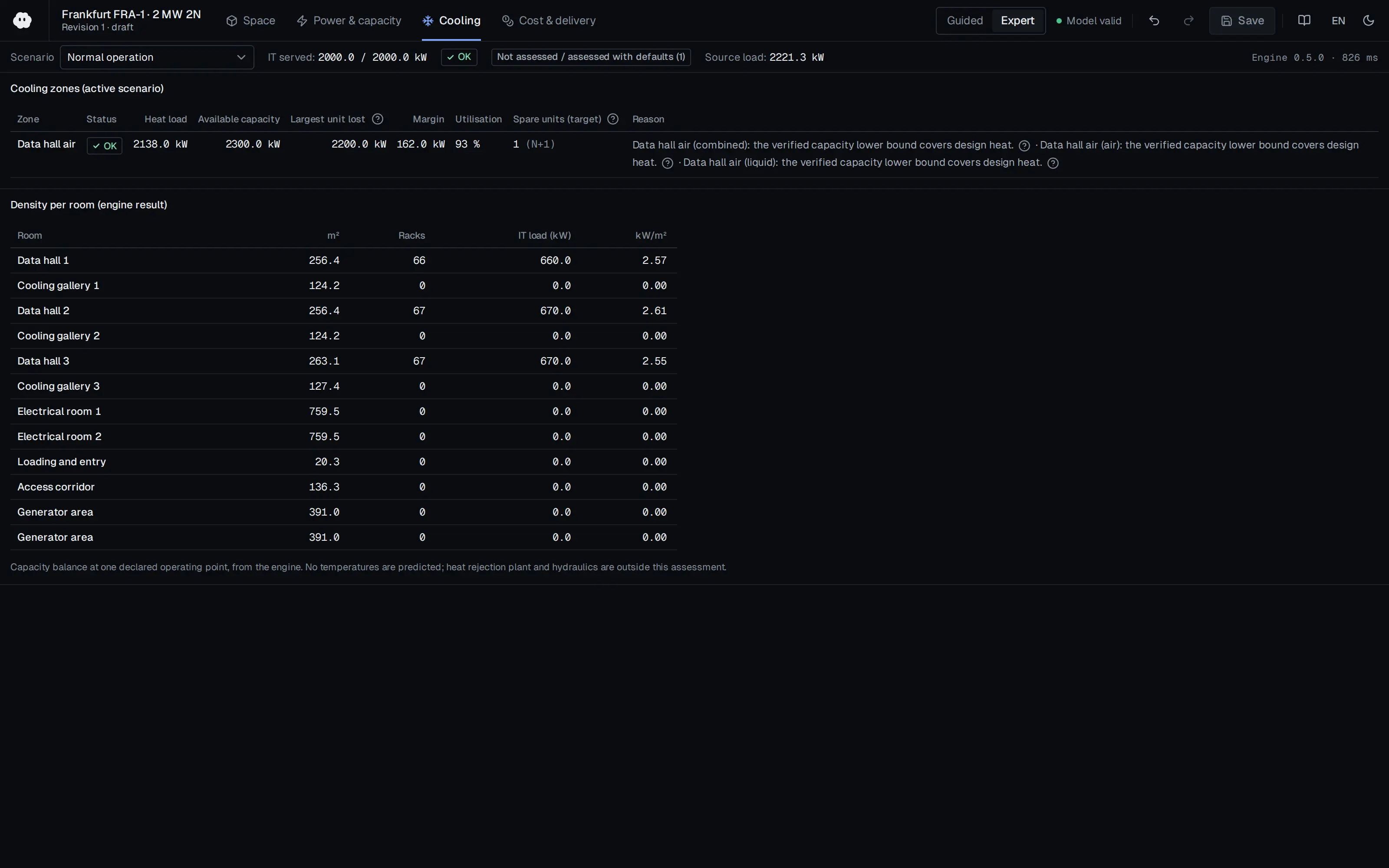
Who should read it
Mechanical designers and HPC facility engineers sizing the heat rejection chain for liquid-cooled IT from climate data.
Related standards
- ASHRAE Liquid Cooling Guidelines for Datacom Equipment Centers (W classes)
Publication details
- Authors
- Henry Coles; Michael Ellsworth; David J. Martinez
- Publisher
- Energy Efficient HPC Working Group / Lawrence Berkeley National Laboratory
- Year
- 2011
- Document number
- LBNL-5128E
- Event
- SC11 (ACM/IEEE Supercomputing 2011), Seattle
- Document language
- English
- Source type
- Government / public
- Access
- Free to read
- Licence
- Copyright retained; citation only — the publisher’s terms apply to the original document
Citation
Henry Coles; Michael Ellsworth; David J. Martinez (2011). "Hot" for Warm Water Cooling (SC11 State of the Practice paper, LBNL-5128E). Energy Efficient HPC Working Group / Lawrence Berkeley National Laboratory. LBNL-5128E. SC11 (ACM/IEEE Supercomputing 2011), Seattle. https://eta-publications.lbl.gov/sites/default/files/lbnl-5128e.pdf
Events on this subject
- ISK-SODEX Istanbul 2027
- SC26 – International Conference for High Performance Computing, Networking, Storage and Analysis
- ASHRAE Winter Conference
All content and rights belong to the respective authors and publishers. SoSo CAD provides only the citation, its own summary and a link to the source, and is not responsible for the sources' content.
Related sources
All sources on this topic
Open Compute Project Foundation 2024
30 C Coolant - A Durable Roadmap for the Future, Revision 1.0 (Oct 2024)
Default the liquid cooling design wizard to an S30 (30 C) TCS supply with a 6 C CDU approach (24 C FWS) and 1.5 LPM per kW.
- Typical CDU flow design is cited as 1.5 LPM per kW; CDU approach temperature is typically 4-8 C.
Energies (MDPI AG) 2023
Cooling Technologies for Internet Data Center in China: Principle, Energy Efficiency, and Applications
In China, define project design targets from GB 50174-2017 temperature and humidity limits (18-27 °C, dew point 5.5-15 °C, RH at most 60%) and provincial PUE caps (for example Guangdong 1.25).
- Cooling accounts for about 35-40% of total IDC energy consumption, the second largest consumer after IT equipment.

Open Compute Project Foundation 2023
Evaluating the Limits of Door Heat Exchanger Solutions Optimized for Open Rack V3
Build a rear-door HX sizing helper that takes rack kW, airflow (cfm), facility water temperature and liquid-capture fraction and returns approach, leaving air temperature and fan power, with 27 C facility water and 30 C air as default reference points.
- Assumptions: 30 C ambient (cold-aisle upper limit), sea level, 12-15 C air delta T, W27 facility water.
Energies (MDPI AG) 2023
Thermal Management and Energy Consumption in Air, Liquid, and Free Cooling Systems for Data Centers: A Review
In preliminary cooling selection, make climate (humidity, haze/dust) and the free-cooling switchover point decisive inputs; direct airside economisers may be unsuitable in haze- and dust-prone regions.
- An indirect evaporative cooling unit in Shenzhen achieved a PUE of 1.249 at 5.3 kW per cabinet.
Frontiers in Energy Research (Frontiers Media SA) 2022
Discussions of Cold Plate Liquid Cooling Technology and Its Applications in Data Center Thermal Management
For loads of 50 kW per rack and above, evaluate a hybrid cold-plate scheme (main loads on cold plates, remaining heat in air) for a PUE target below 1.2.
- Cabinets with enclosed water-cooled backplanes can save nearly 35% of annual energy compared with air-cooled backplanes.
U.S. DOE FEMP 2021
Sandia's Liquid-Cooled Data Center Boosts Efficiency and Resiliency (FEMP success story, DOE/GO-102021-5582, July 2021)
Consider negative-pressure (vacuum) distribution as an option for reducing leak risk in direct liquid cooling; flexible hoses give layout flexibility.
- The system kept CPUs below 50 °C (122 °F); each CDU draws 3.4 kW at full load, about 1.6% of total system power.