
Data Center Liquid Distribution Guidance & Reference Designs, Revision 1.0 (January 8, 2024)
Open Compute Project Foundation · Don Mitchell, John Menoche et al.
OCP Advanced Cooling Facilities guidance on provisioning facility-side liquid distribution so cold plate, immersion and rear-door cooling can be added to new or existing data centers at low cost and risk. It is guidance-level and explicitly not comprehensive.
CC BY-SA 4.0 — share with attribution under the same licence
On this page
Overview
The paper observes that liquid cooled IT has long been used in HPC, usually installed at initial construction, but adding or updating it in later phases is becoming a lifecycle requirement. Because IT refresh happens every 3-5 years, preserving pipe paths and connection points is presented as the way to defer capital cost and avoid disruption. Planning areas are piping sizing and routing, BIM-based reference designs, temperature control, isolation and thermal ride-through, service level agreements, and balancing cost and risk through design, commissioning and procedures. Options for existing facilities include tying into the chilled water system, or bypassing the chiller plant with dry coolers or a closed condenser water loop.
Case 1 covers connection to an existing facility water system, for example by swapping a CRAH or adding tap-offs. Pipe sizing follows Q = volumetric flow x delta T x density x specific heat, and water carries around 3,300 times more heat per volume than air. Glycol and dielectric fluids lower heat capacity; the pipe size versus kW table is conceptual only. Pipe movement matters: the swing from install to peak can exceed 30 °C, and HDPE moves about 7 times as much as stainless steel. CDU needs differ by technology. Cold plate and immersion usually want a CDU to control pressure, quality and temperature, door heat exchangers can often connect directly, and a recirculating pump with a control valve can substitute for a CDU without loop isolation.
Case 2 covers elevated temperature loops above 30 °C. The paper cites ASHRAE TC 9.9's 2021 guidelines with six liquid cooling classes, says cold plate and immersion loops at 35-60 °C are common and can be served by dry heat emission without evaporation, and notes that condensation is not a concern because the highest ASHRAE dew point is 28 °C for Class C and ASHRAE recommends a maximum of 15 °C. Liquid above 50 °C (122 °F) makes heat reuse practical, for example for greenhouses, pools or district heating, improving ERE. A CDU at the facility boundary may still help separate the loop from external liquids, temperatures and pressures.
The risk sections cover thermal ride-through and loss-of-flow, where pump redundancy, backup power and extra loop volume near the IT are recommended. They propose an SLA boundary at the CDU, since ownership of TCS water quality between operator, vendor and tenant is a common problem. FMEA is described through severity, probability and detection of failure, with measures such as locating piping away from or below IT, verifying connection installation and leak detection on threaded, flanged, crimped or fused joints. Tier III and IV implications, SOP, MOP and EOP content, commissioning, BIM content and prefabrication are covered, with appendices on distribution loops, keys to success, FMEA and closed-loop cleaning. The document states it is not comprehensive and has few hard limits.
Key points
- IT refresh occurs every 3-5 years, so preserving pipe routes and tap-off points lets liquid cooling be added later with minimal cost and disruption.
- Heat transfer is Q = volumetric flow x delta T x density x specific heat; by volume water carries around 3,300 times more heat than air.
- Glycol additives and dielectric immersion fluids reduce heat capacity, so they need more volume to move the same heat.
- Temperature swing from installation to peak operation can exceed 30 °C; HDPE has about 7 times the thermal movement of stainless steel.
- Cold plate and immersion loops at 35-60 °C are common and can be served by dry heat rejection without evaporation.
- Liquid above 50 °C (122 °F) is far better for heat reuse than 35 °C (95 °F) air, and improves ERE.
- ASHRAE TC 9.9 (2021) lists a maximum dew point of 28 °C for Class C and recommends a maximum of 15 °C; above 15 °C liquid poses minimal condensation risk.
- Door HX systems can often connect directly to facility water; cold plate and immersion generally use a CDU for pressure, quality and temperature separation.
- The CDU is a logical SLA boundary, with thermal metering of flow, temperature and pressure on the TCS side.
- Tier III concerns cooling supply to the tank, door HX or cold plate, not liquid distribution inside the IT; MTTR is a key availability factor.
Using it in design
- Reserve space for tap-off valves, pipe paths with straight runs, valve and fitting replacement, drainage and condensation collection in the original design.
- Use the Q equation to estimate pipe size against kW and delta T, and confirm it with a licensed engineer, since the paper's table is for concept comparison only.
- Decide per IT technology whether a CDU, recirculating pump or direct connection is used, and place CDUs where maintenance, weight and wet weight can be accommodated.
- Plan thermal ride-through and a loss-of-flow response: redundant pumps, backup power, and extra loop volume nearest the IT.
- Define the SLA boundary and metering at the CDU, and state who maintains and warrants TCS water quality.
- Run an FMEA on connections and require inspection or leak detection according to the joint type and the severity of the location.
Monthly newsletter · free
Keep your reading list current
Once a month: new library sources, changes to Turkish regulations and upcoming data centre events.
SoSo CAD
Check cooling capacity alongside your design
Review zone heat loads, available capacity and the capacity balance after the largest unit is lost in SoSo CAD.
Request a demo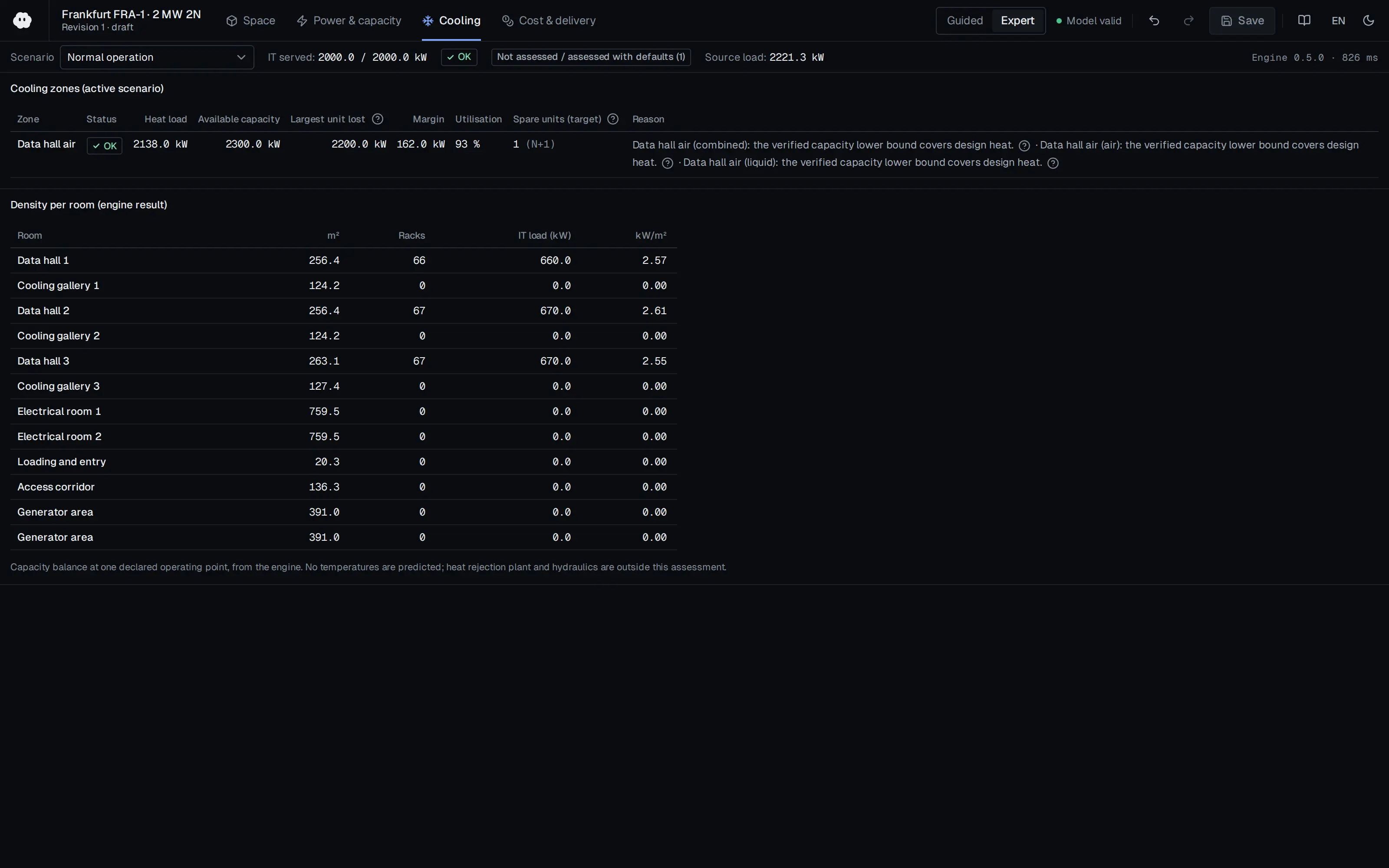
Who should read it
Facility designers, operators and colocation providers planning for future liquid cooled IT, and IT users who need to understand facility-side liquid distribution.
Document contents
- Executive Summary
- 1. Introduction
- 2. Compliance with Open Compute Project Tenets
- 3. Design Considerations
- 3.1 Case 1 - Connection to Existing FWS System
- Planning for Pipe Connections
- Pipe Route Planning
- Pipe Movement
- Pipe Material Selection
- Coolant Distribution Unit (CDU) Planning
- 3.2 Case 2 - Elevated Temperature Loop (>30C) Considerations
- 3.3 Service Level Agreements (SLA) and Risk Considerations
- 3.4 Risk & Reliability Considerations
- 3.5 VDC Enablement of Liquid Cooled ITE in Data Center Life-Cycle
- 4. Conclusion
- Appendix B. Cooling Distribution Loops
- Appendix D. Probability Risk Factor Reduction (FMEA)
- Appendix E. Closed Loop Cleaning Best Practices
Read the document
ocp-acf-reference-design.pdf
CC BY-SA 4.0 — share with attribution under the same licence
The document is provided unaltered because its licence permits redistribution.
Publication details
- Authors
- Don Mitchell; John Menoche; John Gross; Vali Sorell; John Musilli
- Publisher
- Open Compute Project Foundation
- Year
- 2024
- Document language
- English
- Source type
- Industry body
- Access
- Open licence — downloadable
- Licence
- CC BY-SA 4.0 — share with attribution under the same licence
- Licence evidence
- www.opencompute.org
Original licence note
License section of the document states Creative Commons Attribution-ShareAlike 4.0. Attribution required; derivatives/adaptations must stay CC-BY-SA.
Citation
Don Mitchell; John Menoche; John Gross; Vali Sorell; John Musilli (2024). Data Center Liquid Distribution Guidance & Reference Designs, Revision 1.0 (January 8, 2024). Open Compute Project Foundation. https://www.opencompute.org/documents/ocp-acf-reference-design-guidance-white-paper-r1-pdf
Events on this subject
Browse the events calendarAll content and rights belong to the respective authors and publishers. SoSo CAD provides only the citation, its own summary and a link to the source, and is not responsible for the sources' content.
Related sources
All sources on this topic
Open Compute Project Foundation 2026
Whitepaper: Thermal Boundaries in AI Infrastructure - Matching cooling technologies to compute through the power inflection, Version 1.00 (October 2026)
Choose cooling architecture against target rack power and each method's usable envelope: a 45 kW air ceiling (60-80 kW with rear doors), 120-250 kW class cold-plate racks, and the paper's anchor values for announced 600 kW-class racks.
- Practical air-cooled rack ceiling is taken as 45 kW, extendable to about 60-80 kW with rear-door heat exchangers.
Open Compute Project Foundation 2025
Modular Technology Cooling System for "Cloud Scale": Design & Delivery of Liquid to Rack Distribution Systems, Version 1.0 (25 August 2025)
When sizing TCS capacity against electrical capacity, state the cold-plate capture fraction (70-80%) and target delta-T (10 or 20 C) explicitly, and use the roughly doubled delivery at 20 C (4,845 versus 2,422 kW) as design headroom.
- Most IT equipment is designed for a 10 C coolant delta-T, with some designs considering 20 C.
Schneider Electric 2025
Direct Liquid Cooling System Challenges in Data Centers
Use the eight challenges as a DLC readiness checklist in the commissioning and design-review module.
- Heat capture ratio defines the air share: 80% liquid capture leaves 20% for air cooling.

Open Compute Project Foundation 2026
Single-Phase Direct-to-Chip Cold Plate Test Specification, Version 1.0.0 (OCP Cooling Environments: Cold Plate Sub-Project, effective September 3, 2026)
Reference the specification in a cold plate purchase requirement and state which tests, limits and sampling the customer requires, since many limits are examples.
- Flow rate testing goes up to velocities below 1.5 m/s to ensure no erosion or leaks.
Open Compute Project Foundation 2026
Guidelines for Using Dielectric Heat Transfer Fluids in Two-Phase Cold Plate-Based Liquid-Cooled Racks, Revision 1.1 (March 2026)
Apply refrigerant-specific rules to two-phase DLC designs in place of water-loop rules: GWP below 700, A1 safety class, and vapour/liquid line sizing with under 0.2 bar evaporator-to-condenser loss.
- Minimal filtration is about 100 um; ambient during operation should stay within 5-35 C.

Open Compute Project Foundation 2025
Project Deschutes: Data Center Facilities Specification, v0.8.0 (2 MW coolant distribution unit)
Define a 2 MW CDU catalogue template for liquid-cooling layouts: dimensions, wet weight (6910 lb) for slab loading, 74 kW parasitic load, 3 C approach and 0.25 GPM/kW facility flow.
- CDU size 65 x 93.1 x 47.2 in (W x H x D); 6910 lb wet, 5310 lb dry; maximum packaged height 100 in.