
Whitepaper: Thermal Boundaries in AI Infrastructure - Matching cooling technologies to compute through the power inflection, Version 1.00 (October 2026)
Open Compute Project Foundation · Rolf Brink, Mohan J. Kumar et al.
Written by Rolf Brink, Mohan J. Kumar, Steve Mills and Kelley Mullick, this OCP paper argues, through efficiency, economic and physics boundaries and an adoption law, how rising accelerator power forces transitions between cooling methods, and advocates a multi-technology toolbox.
CC BY-SA 4.0 — share with attribution under the same licence
On this page
Overview
The paper argues that cooling, long a supporting utility, now sets the pace at which compute can be deployed. It defines three boundaries bounding every method: the efficiency boundary (the knee of the curve of cooling share against device power), the economic boundary (where total cost of ownership, with energy only one term, turns against the method) and the physics boundary (where no achievable flow, surface or temperature can hold the junction in range, so the method becomes impossible). The gap between the economic and physics boundaries is the avoidance zone, whose width decides whether a transition is abrupt or gradual. Version 1.00 was published on 12 October 2026.
The central claim is the least-disruption law: a new cooling method is adopted only when the incumbent can no longer do the job, because each new method brings dependencies the ecosystem has good reason to defer. Air was forced past its physics boundary in a single generation, cold plate became the default overnight, and a preparation debt followed. In the physics chapter the paper compares specific heat for air at 1,005 J/(kg K), water 4,184, PG25 3,950, fluorocarbon dielectrics 1,050 and oil-based dielectrics 1,850, and notes that die-level heat flux stayed roughly flat at about 50-90 W/cm2 until 2024 while package power tripled through larger die area.
The technology chapters assess air, single- and two-phase cold plate, single- and two-phase immersion, and microfluidics. For air, fan power rises roughly with the cube of flow, so doubling airflow can demand close to eight times the fan power; the practical air-cooled rack ceiling is taken as 45 kW, extendable to about 60-80 kW with rear-door heat exchangers. For a single-phase cold plate at 5 LPM of water and a 10 C allowable coolant rise, sensible heat transport is limited to about 3.46 kW, making roughly 3-4 kW per plate a practical boundary; this is an architectural boundary, not an intrinsic thermodynamic ceiling. The conclusion projects the cold plate physics boundary near 4,000 W for a reticle-class die and notes frontier package power doubling roughly every two years.
The reliability analysis uses typical annual failure rates of 2.5% for an air-cooled GPU, 1.5% for a liquid-cooled GPU, 0.8% for a central CDU, 0.15% per quick disconnect and 0.1% per cold plate per GPU. A shared CDU raises modelled rack-level outage probability from about 0.01% per year (air) to about 0.25% per year (DLC), roughly 25 times, even with N+1 pumps. Rack power anchors are 120-132 kW for GB200 NVL72, about 140 kW for GB300 class, about 230-250 kW for VR200 NVL144 and about 600 kW for the announced Kyber-class Rubin Ultra. The economics use a 200 MW reference case with facility-water delta-T of 8 C for liquid versus 20 C for air, 4% UPS loss and 88% average PSU efficiency.
The conclusion is a toolbox: no method wins on every axis. Air is cheapest and most limited, cold plate is moderate at first and grows expensive when stretched, immersion costs more to stand up but earns it back in reliability and efficiency, two-phase methods reach furthest but pay in fluids, containment and regulation, and microfluidics amplifies the others. The facility is a second forcing function through power, water and land. An epilogue argues commissioning is becoming the bottleneck and must verify not only steady state but load-step response, leak detection and automated isolation, and handoffs between methods. It is an argument-driven paper; many values are modelled or vendor-reported rather than measured standards.
Key points
- Three boundaries are defined: efficiency (knee of the cooling-share curve), economic (total cost of ownership) and physics (impossibility); the gap between the economic and physics boundaries is the avoidance zone.
- Least-disruption law: a new cooling method is adopted only when the incumbent can no longer do the job; air was forced past its physics boundary in one generation and cold plate became the default abruptly.
- Specific heat: air 1,005, water 4,184, PG25 3,950, fluorocarbon dielectrics 1,050, oil-based dielectrics 1,850 J/(kg K).
- Die-level heat flux stayed roughly flat at about 50-90 W/cm2 until 2024 while package power tripled through larger die area.
- Typical annual failure rates used: air-cooled GPU 2.5%, liquid-cooled GPU 1.5%, central CDU 0.8%, quick disconnect 0.15% per fitting, cold plate 0.1% per GPU.
- A shared CDU raises modelled rack-level outage probability from about 0.01% per year (air) to about 0.25% per year (DLC), roughly 25 times, even with N+1 pumps.
- Practical air-cooled rack ceiling is taken as 45 kW, extendable to about 60-80 kW with rear-door heat exchangers.
- Rack power anchors: GB200 NVL72 120-132 kW, GB300 class about 140 kW, VR200 NVL144 about 230-250 kW, Kyber-class Rubin Ultra about 600 kW (announced).
- For a cold plate at 5 LPM water and a 10 C allowable coolant rise, sensible heat transport is limited to about 3.46 kW, so roughly 3-4 kW per cold plate is a practical boundary.
- The economic reference case assumes facility-water delta-T of 8 C for liquid versus 20 C for air, 4% UPS loss and 88% average PSU efficiency; no method wins on every axis.
Using it in design
- Choose cooling architecture against target rack power and each method's usable envelope: a 45 kW air ceiling (60-80 kW with rear doors), 120-250 kW class cold-plate racks, and the paper's anchor values for announced 600 kW-class racks.
- In cold plate design treat 3-4 kW per package as the practical limit and use the 3.46 kW result for 5 LPM and a 10 C rise directly when setting coolant flow and allowable delta-T.
- Note that a shared CDU as a single point of failure raises rack-level outage probability by about 25 times; test redundancy, isolation valves and CDU partitioning against that effect.
- For each method write down its efficiency, economic and physics boundaries and its avoidance zone, and base the decision on total cost of ownership including reliability, capital, labour and floor space rather than energy alone.
- For hybrid architectures (a surface method on the highest-flux accelerator with immersion for the distributed remainder), add the handoffs between methods and load-step response to commissioning acceptance tests.
- Treat the site's power, water and land limits as a second forcing function and compare cooling strategies under those limits for density and heat reuse.
Monthly newsletter · free
Keep your reading list current
Once a month: new library sources, changes to Turkish regulations and upcoming data centre events.
SoSo CAD
Check cooling capacity alongside your design
Review zone heat loads, available capacity and the capacity balance after the largest unit is lost in SoSo CAD.
Request a demo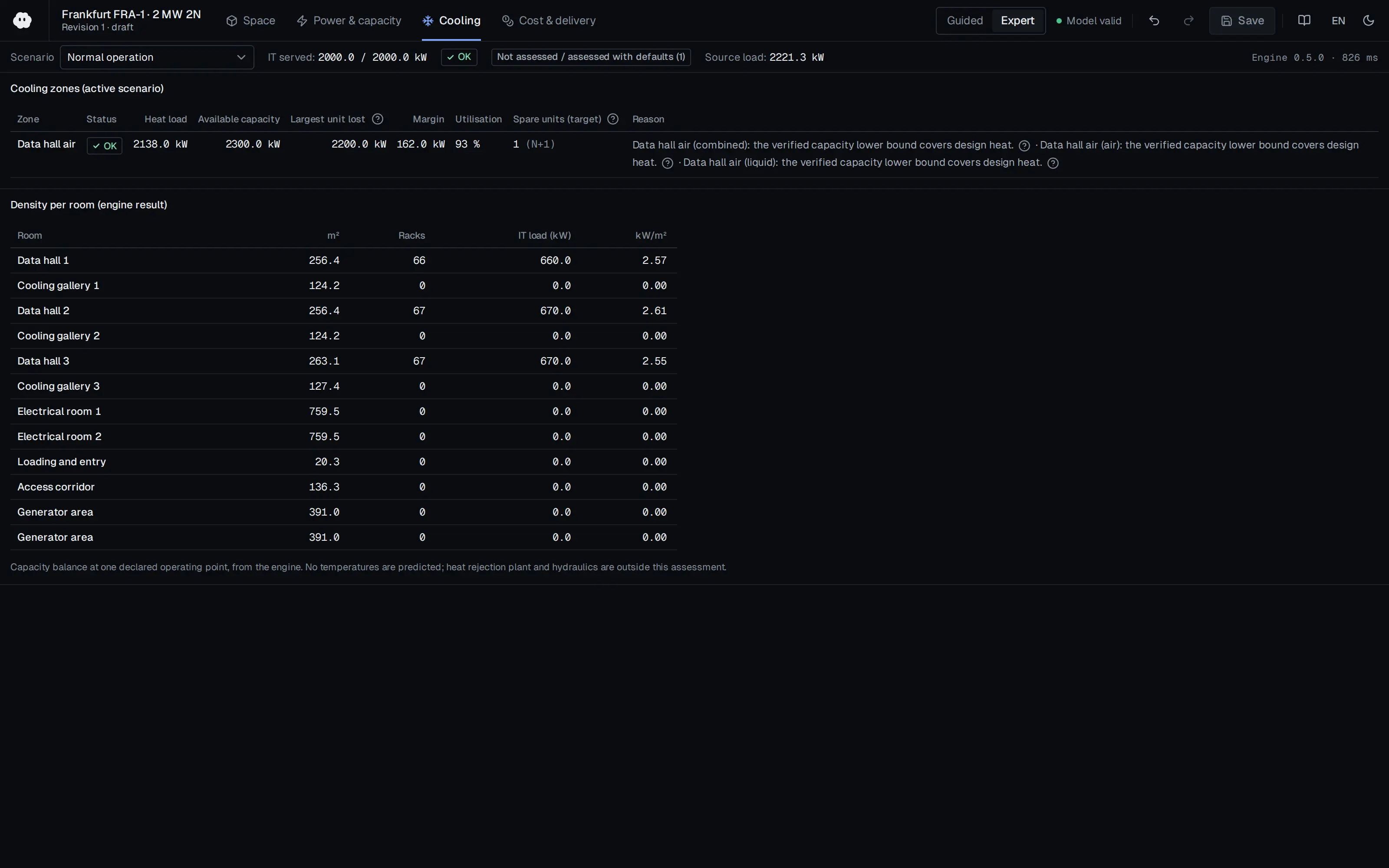
Who should read it
Engineers selecting AI data centre cooling architectures, cooling and IT equipment suppliers, and executives making strategic investment decisions.
Document contents
- Version History and Acknowledgments
- Abstract
- Introduction
- Cooling becomes the constraint
- Runaway power curves are not new
- Why there is no rescue this time
- A different kind of transition
- Open Compute Project Tenets
- The physics that sets the boundaries
- The governing equation
- Why liquids outperform air
- The shrinking temperature budget
- Flux and total power
- The three boundaries
- The efficiency boundary
- The economic boundary
- The physics boundary
- The avoidance zone
- The adoption law
- The shape of the heat
- The thermal path (acquisition, transport and rejection)
- The cooling technologies (air, single-phase cold plate, two-phase cold plate, single-phase immersion, two-phase immersion, microfluidics)
- The economics of cooling
- The toolbox, a multi-technology roadmap
- Epilogue: Commissioning the AI datacenter
- Conclusion
- Appendix A Detailed source material for graphs
- Appendix B Thermohydraulic Limits of Single Phase Cold Plate
- Appendix C Reader's reference
- Appendix D License
Read the document
ocp-thermal-boundaries-ai.pdf
CC BY-SA 4.0 — share with attribution under the same licence
The document is provided unaltered because its licence permits redistribution.
Publication details
- Authors
- Rolf Brink; Mohan J. Kumar; Steve Mills; Kelley Mullick
- Publisher
- Open Compute Project Foundation
- Year
- 2026
- Document language
- English
- Source type
- Industry body
- Access
- Open licence — downloadable
- Licence
- CC BY-SA 4.0 — share with attribution under the same licence
- Licence evidence
- www.opencompute.org
Original licence note
License section of the document states Creative Commons Attribution-ShareAlike 4.0. Attribution required; derivatives/adaptations must stay CC-BY-SA.
Citation
Rolf Brink; Mohan J. Kumar; Steve Mills; Kelley Mullick (2026). Whitepaper: Thermal Boundaries in AI Infrastructure - Matching cooling technologies to compute through the power inflection, Version 1.00 (October 2026). Open Compute Project Foundation. https://www.opencompute.org/wp-content/uploads/2026/10/Thermal-Boundaries-in-AI-Infrastructure.pdf
Events on this subject
Browse the events calendarAll content and rights belong to the respective authors and publishers. SoSo CAD provides only the citation, its own summary and a link to the source, and is not responsible for the sources' content.
Related sources
All sources on this topic
Open Compute Project Foundation 2025
Modular Technology Cooling System for "Cloud Scale": Design & Delivery of Liquid to Rack Distribution Systems, Version 1.0 (25 August 2025)
When sizing TCS capacity against electrical capacity, state the cold-plate capture fraction (70-80%) and target delta-T (10 or 20 C) explicitly, and use the roughly doubled delivery at 20 C (4,845 versus 2,422 kW) as design headroom.
- Most IT equipment is designed for a 10 C coolant delta-T, with some designs considering 20 C.
Open Compute Project Foundation 2024
Data Center Liquid Distribution Guidance & Reference Designs, Revision 1.0 (January 8, 2024)
Reserve space for tap-off valves, pipe paths with straight runs, valve and fitting replacement, drainage and condensation collection in the original design.
- Liquid above 50 °C (122 °F) is far better for heat reuse than 35 °C (95 °F) air, and improves ERE.
Open Compute Project Foundation 2023
Cold Plate Cooling Loop Requirements, Rev 2
Require each vendor to fill in the parameters of importance tables for cold plates, hoses, quick disconnects, loops, manifolds and CDUs so offers can be compared.
- Glycol at 25% or above prevents bacterial growth; dielectric fluids are insulating but cost more and have higher GWP.

Open Compute Project Foundation 2023
Immersion Requirements Rev 2.0, First Amended (Revision 2.10, August 18, 2023)
Compare vendor offers on the same template: request W32 footprint density (kW/m2), full-solution static floor load, ceiling clearance and non-IT power per kW of IT in writing.
- Containment must hold at least 100% of the fluid volume of any single system without breach.

Open Compute Project Foundation 2020
Design Guidelines for Immersion-Cooled IT Equipment, Revision 1.0 (December 2020)
Compare the bill of materials of a server to be immersed (cable jackets, heat-shrink, EPDM capacitors, CMOS battery, relays, thermal paste) against the paper's problem table and obtain a compatibility statement from the fluid supplier for each item.
- In Soxhlet extraction testing, a mass loss below 2% indicates good material compatibility; the 48-hour test gives worst-case results.

Open Compute Project Foundation 2019
OCP ACS Liquid Cooling Cold Plate Requirements Document, Revision 1.0 (October 9, 2019)
Use the parameter tables for cold plates, CDUs, manifolds, couplings and pumps as the data sheet checklist when comparing vendor solutions.
- CPU/GPU cold plates commonly capture 70-75% of IT equipment heat in the hybrid basic class.