
OCP ACS Liquid Cooling Cold Plate Requirements Document, Revision 1.0 (October 9, 2019)
Open Compute Project Foundation · Jessica Gullbrand, Nigel Gore et al.
An early OCP Advanced Cooling Solutions requirements document that defines the terms, selection parameters and safety expectations for cold plate liquid cooling in the technology cooling system (TCS) loop. It is a checklist, not a specification, and is largely qualitative.
CC BY-SA 4.0 — share with attribution under the same licence
On this page
Overview
The document, written by authors from Intel, Iceotope and CPC, sets out requirements that future OCP liquid cooling specifications must meet; a checklist derived from it must be filled in and peer reviewed before a contribution goes to the Incubation Committee. Its scope is the TCS loop, from the CDU to the rack, through the manifold and IT equipment and back, with heat passed to a facility water system (FWS) that is out of scope, as are the IT equipment itself and fully air-cooled designs. It says there is no general guideline for when liquid cooling becomes necessary for CPUs and GPUs, and that the decision belongs in a TCO analysis. It assumes wetted materials are compatible with the coolant and that coolants are never mixed.
The terminology section follows ASHRAE. Cold plates are heat exchangers on the components, with micro-channel designs common for high power, and can be single- or two-phase. Hybrid cooling combines cold plates on high-power parts with air elsewhere and still needs room air conditioning, while full liquid cooling sends all heat to liquid. CDUs may be in-rack, row-level or facility-level and isolate the TCS from the FWS. Rack manifolds distribute flow, and quick disconnect couplings should be drip-less, as hand mate or blind mate types. Coolants covered are water with additives, glycol-based, dielectric and refrigerant fluids; propylene glycol is preferred over ethylene glycol, and glycol at or above 25% prevents bacterial growth while lowering heat transfer.
For each component the document lists a table of parameters of importance to be specified. Cold plate parameters include flow rate, inlet and outlet temperature, active area and filtering requirement. CDU parameters include maximum cooling capacity, liquid volume, approach temperature, pump capacity, PQ curve, power draw at 100%, 80% and 30% load, and connectors. Manifold velocity should stay within 1.5 to 2.1 m/s, depending on pipe diameter, to avoid erosion per ASHRAE. Coupling parameters include burst pressure, spillage and connection cycles; pump parameters include MTBF, IP rating and suction height. The document stresses that operating and burst pressures differ, and gives typical TCS operating pressure as 140-450 kPa (20-65 psi) for in-rack and row CDUs.
The requirements chapter covers certification (UL and FCC in the US, CE in Europe), pressure safety and risk management. IEC 62368-1 requires leak tests at 3 times normal operating pressure and 2 times under abnormal and single-fault conditions, while ASME B31.3 requires 1.5 times design pressure, and loops must meet the highest. It defines four IT equipment classes (hybrid basic, intermediate, advanced, full liquid), notes that CPU/GPU cold plates commonly capture 70-75% of IT heat, and two liquid-ready rack classes with or without a door heat exchanger. Sensor tiers follow ASHRAE Tier 2 and Tier 3, Redfish telemetry is referenced, and leak detection (indirect or direct) and intervention (manual or automatic) are classified.
Key points
- The document covers only the TCS loop (CDU to rack, manifold, IT equipment and back); the facility water system is out of scope.
- Hybrid cooling puts cold plates on high-power parts and air on the rest and still needs room air conditioning; full liquid cooling sends all heat to liquid.
- CPU/GPU cold plates commonly capture 70-75% of IT equipment heat in the hybrid basic class.
- Typical TCS operating pressure is 140-450 kPa (20-65 psi) with in-rack and row-level CDUs; a facility CDU may give higher pressure.
- IEC 62368-1 requires leak tests at 3x normal operating pressure and 2x under abnormal and single-fault conditions; ASME B31.3 requires 1.5x design pressure; test to the highest.
- Manifold fluid velocity should not exceed about 1.5-2.1 m/s depending on pipe diameter, to avoid erosion (per ASHRAE).
- Glycol at 25% or more prevents bacterial growth but reduces heat transfer; propylene glycol is preferred over ethylene glycol for toxicity.
- Quick disconnects should be drip-less; operating and burst pressure are distinct parameters.
- Minimum liquid cooling sensors align with ASHRAE DCIM Tier 2 and advanced sensors with Tier 3; Redfish is the telemetry interface.
- Leak detection is classed as indirect (pressure, flow, temperature analysis) or direct (leak rope or spot detectors); intervention as manual or automatic.
Using it in design
- Use the parameter tables for cold plates, CDUs, manifolds, couplings and pumps as the data sheet checklist when comparing vendor solutions.
- Classify the IT equipment as hybrid basic, intermediate, advanced or full liquid and use the capture fraction to size the residual room air load.
- Pick the rack class (with or without door heat exchanger) according to whether the room must be heat neutral.
- Set the TCS test pressure to the highest of IEC 62368-1 and ASME B31.3 multiples and size the loop for 140-450 kPa operating pressure.
- Decide the leak detection (indirect, direct) and intervention (manual, automatic) level against the uptime requirement and sensor cost.
- Cap manifold velocity at the limits cited, and specify coolant, filtration and wetted-material compatibility together.
Monthly newsletter · free
Keep your reading list current
Once a month: new library sources, changes to Turkish regulations and upcoming data centre events.
SoSo CAD
Check cooling capacity alongside your design
Review zone heat loads, available capacity and the capacity balance after the largest unit is lost in SoSo CAD.
Request a demo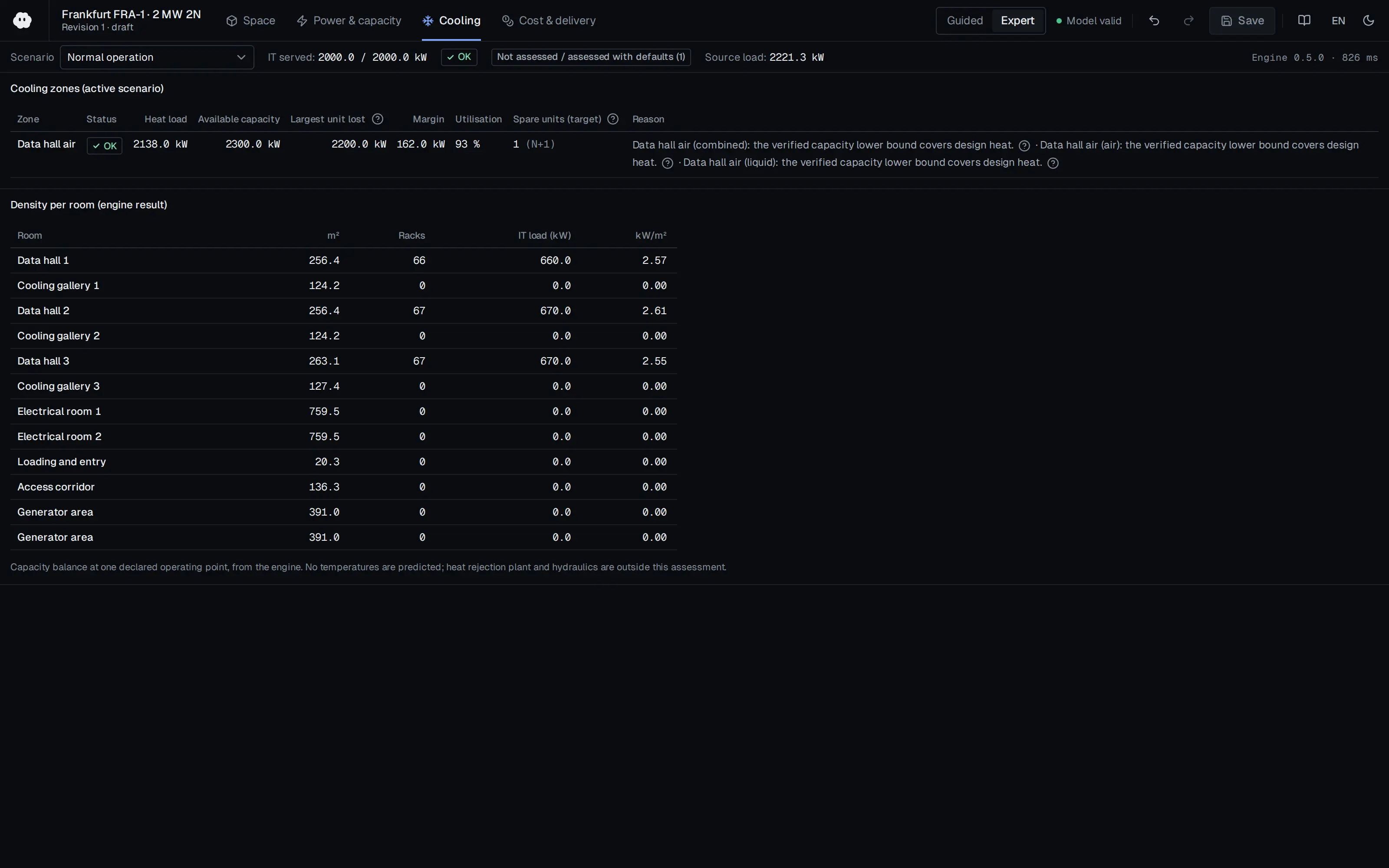
Who should read it
Liquid cooling designers, rack and CDU vendors, and facility engineers who need a consistent way to specify and compare TCS loop components.
Document contents
- Introduction
- Terminology
- Liquid Cooling Technology Definitions
- Liquid Cooling Cold Plates
- Hybrid Cooling
- Full Liquid Cooling
- Single- and Two-Phase Cooling Liquids
- Coolant Distribution Unit
- Rack Manifold
- Quick Disconnect Couplings
- Cooling Components Selection and Parameters of Importance
- Cooling Liquid Selection
- Cold Plate Selection
- Coolant Distribution Unit Selection
- Rack Manifold Selection
- Quick Disconnect Coupling Selection
- Pump Selection
- Liquid Cooling Requirements
- Pressure Safety Requirements
- Risk Management
- Liquid Cooling Classifications
- Sensor Requirements
- DMTF Redfish
- Leakage Detection and Intervention Requirements
- Comparison Metrics
Read the document
ocp-acs-cold-plate-requirements.pdf
CC BY-SA 4.0 — share with attribution under the same licence
The document is provided unaltered because its licence permits redistribution.
Publication details
- Authors
- Jessica Gullbrand; Nigel Gore; Jason Matteson; Elizabeth Langer
- Publisher
- Open Compute Project Foundation
- Year
- 2019
- Document language
- English
- Source type
- Industry body
- Access
- Open licence — downloadable
- Licence
- CC BY-SA 4.0 — share with attribution under the same licence
- Licence evidence
- www.opencompute.org
Original licence note
License section of the document states Creative Commons Attribution-ShareAlike 4.0. Attribution required; derivatives/adaptations must stay CC-BY-SA.
Citation
Jessica Gullbrand; Nigel Gore; Jason Matteson; Elizabeth Langer (2019). OCP ACS Liquid Cooling Cold Plate Requirements Document, Revision 1.0 (October 9, 2019). Open Compute Project Foundation. https://www.opencompute.org/documents/ocp-acs-liquid-cooling-cold-plate-requirements-pdf
Events on this subject
- 7x24 Exchange Spring Conference
- 7x24 Exchange Fall Conference
- SC26 – International Conference for High Performance Computing, Networking, Storage and Analysis
All content and rights belong to the respective authors and publishers. SoSo CAD provides only the citation, its own summary and a link to the source, and is not responsible for the sources' content.
Related sources
All sources on this topic
Open Compute Project Foundation 2026
Whitepaper: Thermal Boundaries in AI Infrastructure - Matching cooling technologies to compute through the power inflection, Version 1.00 (October 2026)
Choose cooling architecture against target rack power and each method's usable envelope: a 45 kW air ceiling (60-80 kW with rear doors), 120-250 kW class cold-plate racks, and the paper's anchor values for announced 600 kW-class racks.
- Practical air-cooled rack ceiling is taken as 45 kW, extendable to about 60-80 kW with rear-door heat exchangers.
Open Compute Project Foundation 2025
Modular Technology Cooling System for "Cloud Scale": Design & Delivery of Liquid to Rack Distribution Systems, Version 1.0 (25 August 2025)
When sizing TCS capacity against electrical capacity, state the cold-plate capture fraction (70-80%) and target delta-T (10 or 20 C) explicitly, and use the roughly doubled delivery at 20 C (4,845 versus 2,422 kW) as design headroom.
- Most IT equipment is designed for a 10 C coolant delta-T, with some designs considering 20 C.
Vertiv 2026
Transforming Colocation Facilities to Meet Demand for AI Compute
Give the rack/pod model a liquid fraction (default about 70% for direct-to-chip) so residual air load is computed automatically.
- Average multi-node AI pod density is projected to rise from 40-100 kW to 100-250 kW.
Open Compute Project Foundation 2026
Guidelines for Using Dielectric Heat Transfer Fluids in Two-Phase Cold Plate-Based Liquid-Cooled Racks, Revision 1.1 (March 2026)
Apply refrigerant-specific rules to two-phase DLC designs in place of water-loop rules: GWP below 700, A1 safety class, and vapour/liquid line sizing with under 0.2 bar evaporator-to-condenser loss.
- Minimal filtration is about 100 um; ambient during operation should stay within 5-35 C.

Open Compute Project Foundation 2026
OCP Cooling Environments: Cold Plate Sub-Project Design Specification, Universal Quick Disconnect (UQD), v2.0.0 (effective September 22, 2026)
Select size (02-08) by rack or server loop flow: rated flows run from 2.27 to 17.79 L/min; estimate pressure drop from the Cv range and ask for correction or extra testing where the fluid differs from water.
- Cv ranges: 0.30-0.43 for size 02, 1.1-1.6 for 04, 2.2-3.3 for 06 and 3.6-5.6 for 08.

Open Compute Project Foundation 2025
Project Deschutes: Data Center Facilities Specification, v0.8.0 (2 MW coolant distribution unit)
Define a 2 MW CDU catalogue template for liquid-cooling layouts: dimensions, wet weight (6910 lb) for slab loading, 74 kW parasitic load, 3 C approach and 0.25 GPM/kW facility flow.
- CDU size 65 x 93.1 x 47.2 in (W x H x D); 6910 lb wet, 5310 lb dry; maximum packaged height 100 in.