
Free Cooling for Data Centers
STULZ
This 2015 STULZ document compares five free-cooling (economiser) options for data centres by their pros and cons. Its main message is that the move to supply-air control and higher ASHRAE temperatures has extended free-cooling hours.
On this page
Overview
The paper surveys five topologies: direct outside air, indirect air/air plate exchangers, thermal wheels, CRAC units with glycol dry coolers, and CRAH units with chillers. Each comes with a short list of pros and cons. Every free-cooling variant listed keeps 100 % mechanical cooling as backup.
The shift in temperature level is the heart of the explanation. Older rooms controlled return air at 22-24 C, which produced supply air around 12 C. Current practice controls supply air at 18-27 C per ASHRAE TC 9.9 2011, giving return air of 25-40 C; overall the level is about 10 C higher, which lengthens free-cooling hours.
The differences between options are quantified. Thermal-wheel indirect systems need 4-6 times more indoor footprint than two-stage systems. With a CRAC plus dry cooler, mixed (partial free-cooling) mode begins when outdoor air is about 5 C below the room return-air temperature. Chiller-based CRAH systems run relatively low, typically glycol-mixed chilled-water temperatures, which limits their free-cooling hours. Humidity issues with direct outside air are also noted.
Key points
- Older practice: return air at 22-24 C, supply air around 12 C.
- Current practice: supply air 18-27 C (ASHRAE TC 9.9 2011), return air 25-40 C; overall about 10 C higher.
- All free-cooling variants keep 100 % mechanical cooling backup.
- Thermal-wheel indirect systems need 4-6x more indoor footprint than two-stage systems.
- CRAC plus dry cooler enters mixed mode when outdoor air is about 5 C below return-air temperature.
- Chiller-based CRAH runs low, glycol-mixed chilled water, limiting free-cooling hours.
- Humidity control is flagged as an issue with direct outside air.
Using it in design
- Model the cooling-topology choice with five options (direct air, indirect plate, thermal wheel, CRAC with glycol dry cooler, CRAH with chiller economiser), each with a footprint multiplier and an economiser start condition.
- Recompute free-cooling hours whenever the user changes the ASHRAE inlet target, because the hours depend on the supply setpoint.
- Assume full mechanical backup by default.
- When a thermal wheel is chosen, carry the 4-6x indoor footprint into the layout check.
Monthly newsletter · free
Keep your reading list current
Once a month: new library sources, changes to Turkish regulations and upcoming data centre events.
SoSo CAD
Check cooling capacity alongside your design
Review zone heat loads, available capacity and the capacity balance after the largest unit is lost in SoSo CAD.
Request a demo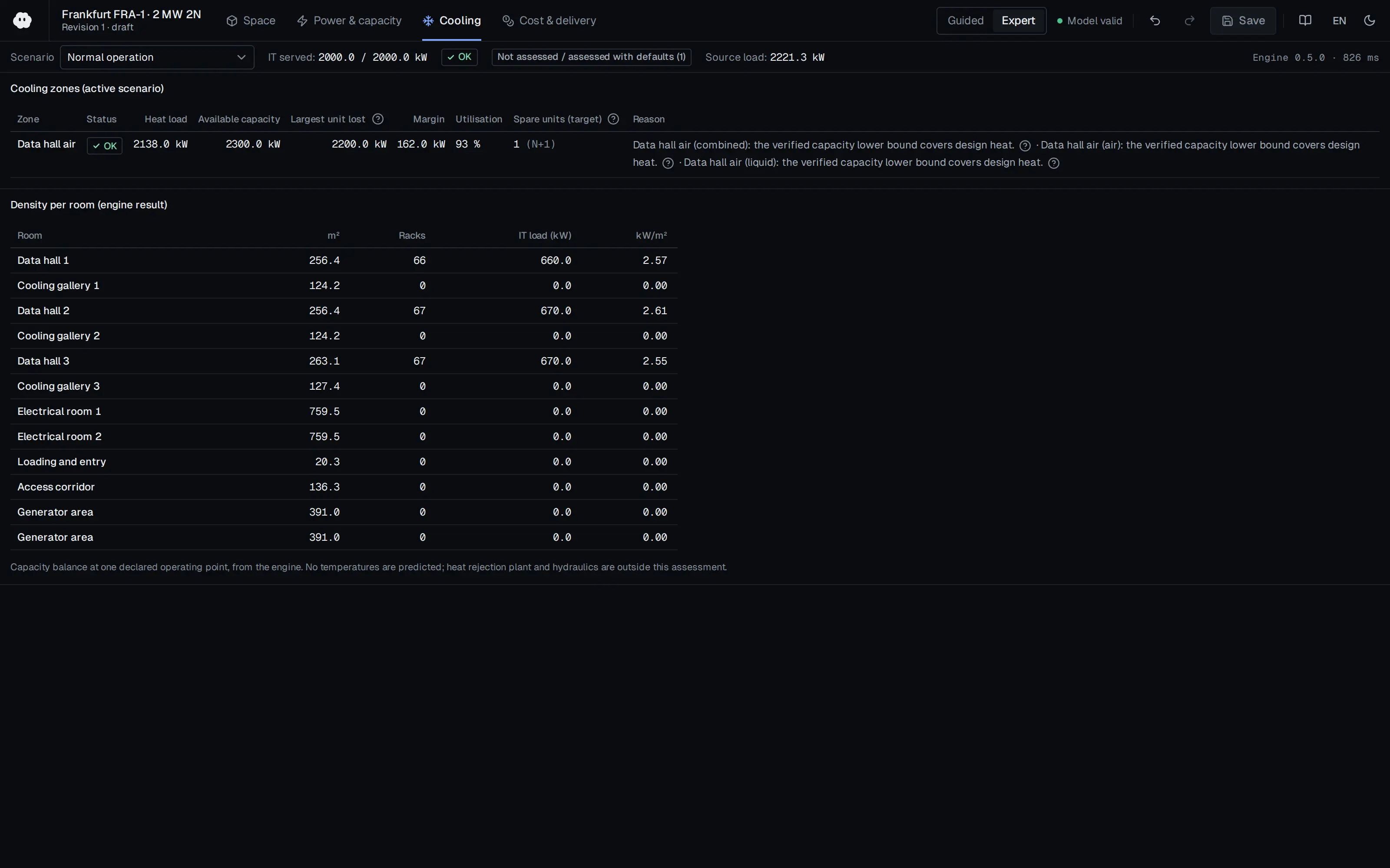
Who should read it
HVAC and data-centre designers comparing cooling topologies and free-cooling potential at an early stage.
Related standards
- ASHRAE TC 9.9 (2011)
- EU Code of Conduct on Data Centres
- EN 50600
Publication details
- Authors
- STULZ
- Publisher
- STULZ
- Year
- 2015
- Document number
- Release 1, September 2015
- Document language
- English
- Source type
- Manufacturer
- Access
- Free to read
- Licence
- Copyright retained; citation only — the publisher’s terms apply to the original document
Citation
STULZ (2015). Free Cooling for Data Centers. STULZ. Release 1, September 2015. https://www.approvedbusiness.co.uk/storage/brochures/7909-stulz-white-paper-free-cooling-for-data-centers-v1.pdf
Events on this subject
Browse the events calendarAll content and rights belong to the respective authors and publishers. SoSo CAD provides only the citation, its own summary and a link to the source, and is not responsible for the sources' content.
Related sources
All sources on this topic
Applied System Innovation (MDPI AG) 2026
Proactive Cooling Control Algorithm for Data Centers Based on LSTM-Driven Predictive Thermal Analysis
For predictive cooling control, plan at least one inlet and one outlet temperature sensor per rack; below that, prediction error rose by about 22%.
- The LSTM uses a 60 min input window and a 30 min prediction horizon, with a reported RMSE of 0.25 and R² of 0.985.
Sustainability (MDPI AG) 2026
Retrofit Optimization of Raised-Floor Plenum Thermal Performance for Energy-Efficient and Sustainable Operation of Non-Standard Campus Data Centers
For plenum imbalance, consider a 50%-perforated transverse baffle about 0.3 m from the unit outlet; 50% open gave a smaller resistance increase than 30% (8.5% against 18.7%).
- For S4, SHI fell from 0.42 to 0.35, maximum rack inlet temperature fell from 27.2 °C to 26.7 °C, and all racks met the 27 °C ASHRAE recommended limit.
European Commission JRC 2025
2025 Best Practice Guidelines for the EU Code of Conduct on Data Centre Energy Efficiency (JRC141521, EUR 40267)
Design the facility to operate within the ASHRAE Class A2 allowable range and require A2 operation within warranty in IT procurement; plan separate environmental zones (practice 5.3.4) for legacy equipment.
- IT equipment AC/DC power converters should be rated at 90% efficiency or better across expected load ranges.
U.S. DOE FEMP / NREL 2024
Best Practices Guide for Energy-Efficient Data Center Design (Revised July 2024)
Weigh the supply air setpoint against server fan energy: raise it in small steps within the ASHRAE recommended range so the most demanding inlet nears 80 °F, only after air management is in place, and control to IT inlet temperature rather than return temperature.
- Compute racks reached 60 kW in 2013, and recent liquid-cooled racks exceed 125 kW.
Energies (MDPI AG) 2018
Analysis of Air-Side Economizers in Terms of Cooling-Energy Performance in a Data Center Considering Exhaust Air Recirculation
In airside economiser design, plan exhaust grilles and the building envelope so recirculation stays below 5%; 15% recirculation raised energy about 6.1% for direct and 9% for indirect.
- The authors recommend placing exhaust-air grilles so recirculation is below 5%, or handling it in the envelope plan at design stage.
European Commission JRC 2018
2018 Best Practice Guidelines for the EU Code of Conduct on Data Centre Energy Efficiency - Version 9.1.0 (JRC110666, EUR 29103 EN)
Keep the 2018 edition practices as a selectable compliance baseline for projects designed in 2018.
- 5.4.1.8 (value 5): investigate free cooling in all new builds and retrofits.