
Liquid to Liquid CDU Test Methodology and Performance Rating, Revision 1.0
Open Compute Project Foundation · Wondimu, B., Kung, E. et al.
An OCP white paper by authors from Intel, CoolIT and Meta that gives liquid-to-liquid coolant distribution units (CDUs), which separate the technology cooling system (TCS) from the facility water system (FWS), a common test method and capacity-rating format. It aims to produce a comparable kW rating for in-rack and in-row CDUs.
CC BY-SA 4.0 — share with attribution under the same licence
On this page
Overview
The document says CDU performance definitions vary from supplier to supplier because of a lack of standardisation in design, rating and reporting. A liquid-to-liquid CDU is heat exchanger hardware that isolates the IT-side flow network from the facility loop and controls flow, pressure and temperature. Two main types are defined: the in-rack CDU, a standard U form factor chassis (for example 4U or 5U) connected to rack manifolds, and the in-row CDU, usually of larger capacity and serving several racks. Both connect to the facility water system through a heat exchanger.
The basic requirements table gives operating coolant temperature of 17-65 C (coolant must be delivered at least 2 C above dew point per ASHRAE), non-operating -40 to 85 C, relative humidity 10-90%, a 10-year service life (taken as the time for 10% of a pump population to fail), a primary filter of at most 200 microns and a secondary filter of at most 50 microns. Pump redundancy (N+1 or more) is essential to keep service during repair; wetted parts must be compatible with the coolant and 304/316 stainless steel is commonly used. Pressure supplied to the TCS can be as high as 100 psi (690 kPa), so TCS components must be designed for it.
Thermal performance is stated through approach temperature difference (ATD = TCS supply temperature minus FWS supply temperature) against the heat load supported at a given flow. Pressure head (TCS P-Q curves) and facility-side flow impedance are measured separately, with and without quick disconnects shown. The recommended design flow for rating is 1.5 LPM/kW, said to support most current chips. An in-rack CDU rating is X kW where TCS head is at least 25 psi at X x 1.5 LPM, FWS impedance is at most 75 psi and ATD is 5 C. For in-row units the TCS head is at least 40 psi.
Reliability tests cover hydrostatic pressure (IEC 62368-1 or ASME B31.1/B31.3), chemical compatibility (coupon tests, ASTM B117 salt spray, fluid analysis by ICP-MS, GC-MS, LC-MS and ion chromatography), dynamic testing (vibration IEC 60068-2-64, shock IEC 60068-2-27, ISTA shipping) and thermal cycling, with a pressure test after every mechanical and thermal test to check for leaks. Typical filter sizes are 25-50 microns on the TCS and 150-250 microns on the facility side. The paper presents itself as general test requirements and sets no vendor-specific acceptance threshold; it lists typical regulatory requirements for safety, EMC and material compliance.
Key points
- Basic requirements: operating coolant 17-65 C (at least 2 C above dew point), non-operating -40 to 85 C, 10-90% RH, 10-year service life, primary filter at most 200 microns, secondary at most 50 microns.
- Thermal performance is specified as ATD = TCS supply temperature minus FWS supply temperature versus heat load at given flows.
- A recommended design flow of 1.5 LPM/kW is said to support most current chips.
- In-rack CDU rating: X kW where TCS head is at least 25 psi at X x 1.5 LPM, FWS impedance at most 75 psi and ATD 5 C.
- In-row CDU rating: as in-rack, but TCS head at least 40 psi at X x 1.5 LPM.
- Reporting must state fluid type (water on the FWS, propylene glycol on the TCS), FWS temperature or ASHRAE water class, and flow rate.
- Pressure supplied to the TCS can be up to 100 psi (690 kPa), and TCS components should be designed for it.
- Typical filtration is 25-50 microns on the TCS and 150-250 microns on the facility side; hot-swappable filters and pumps are best practice.
- Hydrostatic testing per IEC 62368-1 or ASME B31.1/B31.3, a pressure test after every performance test, then shock and vibration followed by leak checks.
- N+1 or greater pump redundancy keeps service during repair, and a leak sensor rope is the common protection.
Using it in design
- Store CDU capacity in the catalogue using this rating basis (kW at 5 C ATD, 1.5 LPM/kW, head and FWS impedance) so units from different vendors can be compared, and derate when the design ATD or flow differs.
- In the liquid-loop calculator default to 1.5 LPM/kW and check that TCS supply is at least 2 C above room dew point.
- Specify 25-50 micron filtration on the TCS and 150-250 micron on the FWS.
- When selecting a CDU, compare the TCS P-Q curve (including quick disconnects) with in-rack network impedance, and the FWS curve with facility pump capacity.
- Ask the supplier for hydrostatic, shock/vibration and thermal-cycling test reports and wetted-material compatibility evidence.
- Choose in-rack CDUs at a U height that fits an EIA-310 19 in or ORv3 rack (4U, 5U); for in-row units check rack-size form (42U, 48U).
Monthly newsletter · free
Keep your reading list current
Once a month: new library sources, changes to Turkish regulations and upcoming data centre events.
SoSo CAD
Check cooling capacity alongside your design
Review zone heat loads, available capacity and the capacity balance after the largest unit is lost in SoSo CAD.
Request a demo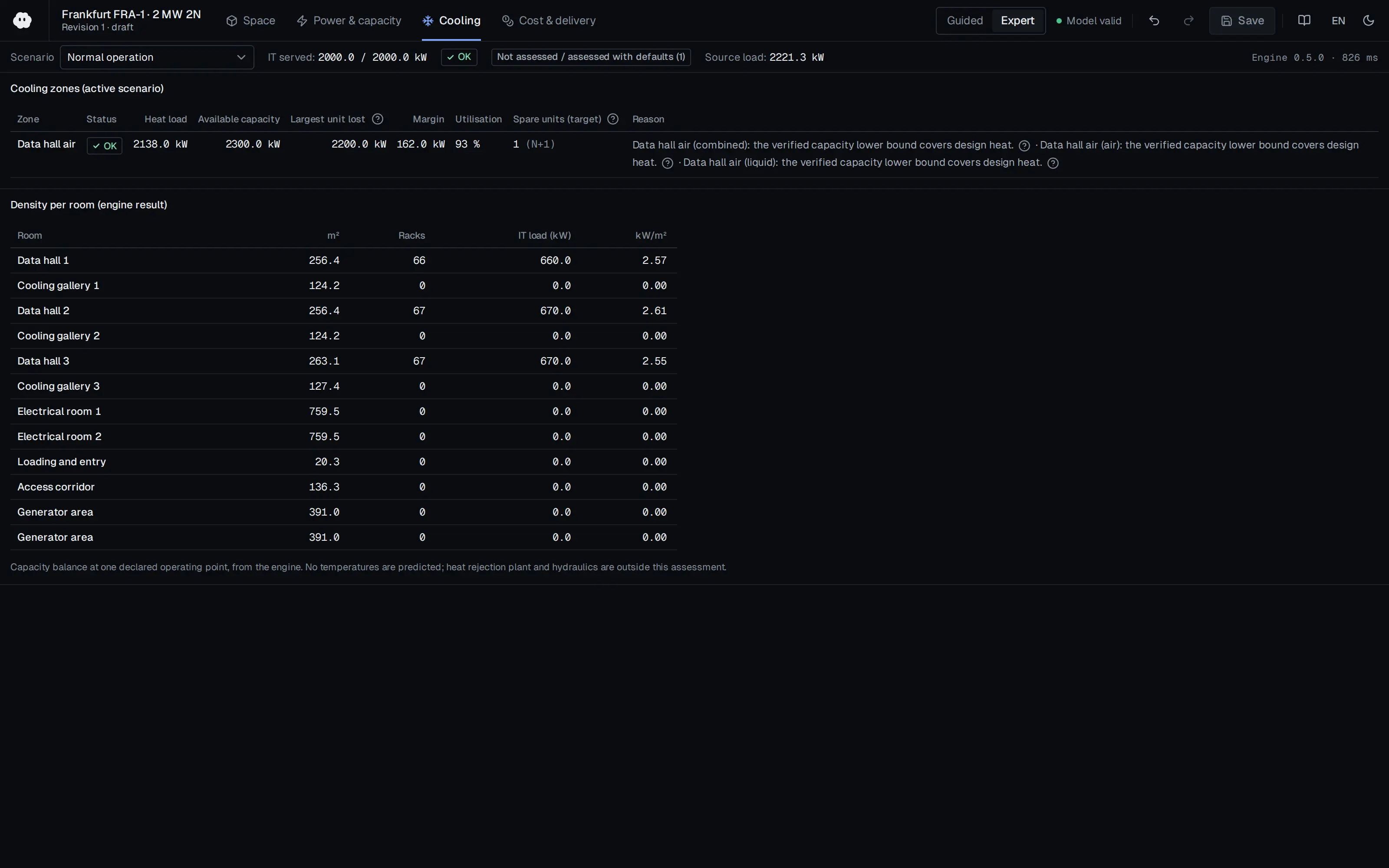
Who should read it
Mechanical engineers who design or buy CDUs, liquid cooling integrators and test laboratories.
Document contents
- Introduction
- Compliance with Open Compute Project Tenets
- CDU Development Guidelines
- General Liquid to Liquid CDU Requirements
- Basic L-L CDU Design
- Mechanical Design
- Material Selection
- Pump Selection
- Cooling Loop Integration
- Sensors & Controllers
- Quality Control
- Surface Treatment
- Cleaning
- Fluid Servicing
- Filling & Flushing the System
- Filter Servicing
- Test Methodology
- Mechanical Testing
- Performance Testing & Reporting
- Thermal Performance
- TCS Pressure Head
- FWS Flow Impedance
- Recommendation on Performance Reporting
- Reliability Testing
- Hydrostatic Pressure Testing
- Chemical Compatibility Testing
- Dynamic Testing
- Thermal Cycling
- Typical Regulatory Requirements
- Conclusion
- Glossary
- References
Related standards
- ASHRAE TC 9.9 Liquid Cooling Guidelines
- IEC 62368-1
- ASME B31.1
- ASME B31.3
- OCP Project Deschutes CDU specification
Read the document
ocp-l2l-cdu-test-methodology.pdf
CC BY-SA 4.0 — share with attribution under the same licence
The document is provided unaltered because its licence permits redistribution.
Publication details
- Authors
- Wondimu, B.; Kung, E.; Zhou, D. (Intel); Zakaib, B. (CoolIT Systems); Chu, C. (Meta)
- Publisher
- Open Compute Project Foundation
- Year
- 2024
- Document number
- Rev 1.0
- Document language
- English
- Source type
- Industry body
- Access
- Open licence — downloadable
- Licence
- CC BY-SA 4.0 — share with attribution under the same licence
- Licence evidence
- www.opencompute.org
Original licence note
Pages 1-2 and page footers state the work is licensed under a Creative Commons Attribution-ShareAlike 4.0 International License.
Citation
Wondimu, B.; Kung, E.; Zhou, D. (Intel); Zakaib, B. (CoolIT Systems); Chu, C. (Meta) (2024). Liquid to Liquid CDU Test Methodology and Performance Rating, Revision 1.0. Open Compute Project Foundation. Rev 1.0. https://www.opencompute.org/documents/ocp-wp-l-lcdu-test-methodology-performance-rating-r1-pdf/
Events on this subject
Browse the events calendarAll content and rights belong to the respective authors and publishers. SoSo CAD provides only the citation, its own summary and a link to the source, and is not responsible for the sources' content.
Related sources
All sources on this topic
Open Compute Project Foundation 2026
Whitepaper: Thermal Boundaries in AI Infrastructure - Matching cooling technologies to compute through the power inflection, Version 1.00 (October 2026)
Choose cooling architecture against target rack power and each method's usable envelope: a 45 kW air ceiling (60-80 kW with rear doors), 120-250 kW class cold-plate racks, and the paper's anchor values for announced 600 kW-class racks.
- Practical air-cooled rack ceiling is taken as 45 kW, extendable to about 60-80 kW with rear-door heat exchangers.
Open Compute Project Foundation 2026
Guidelines for Using Dielectric Heat Transfer Fluids in Two-Phase Cold Plate-Based Liquid-Cooled Racks, Revision 1.1 (March 2026)
Apply refrigerant-specific rules to two-phase DLC designs in place of water-loop rules: GWP below 700, A1 safety class, and vapour/liquid line sizing with under 0.2 bar evaporator-to-condenser loss.
- Minimal filtration is about 100 um; ambient during operation should stay within 5-35 C.

Open Compute Project Foundation 2025
Project Deschutes: Data Center Facilities Specification, v0.8.0 (2 MW coolant distribution unit)
Define a 2 MW CDU catalogue template for liquid-cooling layouts: dimensions, wet weight (6910 lb) for slab loading, 74 kW parasitic load, 3 C approach and 0.25 GPM/kW facility flow.
- CDU size 65 x 93.1 x 47.2 in (W x H x D); 6910 lb wet, 5310 lb dry; maximum packaged height 100 in.
Open Compute Project Foundation 2025
Modular Technology Cooling System for "Cloud Scale": Design & Delivery of Liquid to Rack Distribution Systems, Version 1.0 (25 August 2025)
When sizing TCS capacity against electrical capacity, state the cold-plate capture fraction (70-80%) and target delta-T (10 or 20 C) explicitly, and use the roughly doubled delivery at 20 C (4,845 versus 2,422 kW) as design headroom.
- Most IT equipment is designed for a 10 C coolant delta-T, with some designs considering 20 C.
Open Compute Project Foundation 2024
Data Center Liquid Distribution Guidance & Reference Designs, Revision 1.0 (January 8, 2024)
Reserve space for tap-off valves, pipe paths with straight runs, valve and fitting replacement, drainage and condensation collection in the original design.
- Liquid above 50 °C (122 °F) is far better for heat reuse than 35 °C (95 °F) air, and improves ERE.
Open Compute Project Foundation 2019
OCP ACS Liquid Cooling Cold Plate Requirements Document, Revision 1.0 (October 9, 2019)
Use the parameter tables for cold plates, CDUs, manifolds, couplings and pumps as the data sheet checklist when comparing vendor solutions.
- CPU/GPU cold plates commonly capture 70-75% of IT equipment heat in the hybrid basic class.