
UFC 3-520-01, Interior Electrical Systems (16 January 2025)
U.S. DoD (UFC) · Naval Facilities Engineering Systems Command (NAVFAC), U.S. Army Corps of Engineers (USACE) et al.
From the US Department of Defense's Unified Facilities Criteria series, this document sets mandatory criteria for interior electrical design of military facilities: system voltage, dry-type transformers, distribution equipment, spare capacity, surge protective devices (SPDs), conductors and stationary batteries.
U.S. public domain — U.S. Government work; free to reuse
On this page
Overview
UFC 3-520-01 supersedes the 06 October 2015 edition and is mandatory for planning, design, construction, sustainment, restoration and modernisation of DoD-owned facilities under all delivery methods. Its scope extends about 5 feet beyond the facility envelope; exterior systems fall under UFC 3-550-01. It applies together with NFPA 70, and facilities outside the United States must also meet host nation standards. It points to UFC 3-560-01 for electrical safety and energised work and to UFC 4-010-06 for control system cybersecurity. For projects designated Critical Operations Power Systems (COPS), stricter UFC requirements prevail over NFPA 70; this UFC does not address COPS. It is not data-centre specific and defers to NFPA 70 and other UFCs on many topics.
For voltage, 240/120 V is used for single-phase-only facilities, three-phase four-wire 208Y/120 V for demand loads under 150 kVA, and 480Y/277 V for demand loads above 150 kVA unless 208Y/120 V is shown to be more cost-effective. Distribution frequency is 60 Hz, using the local frequency where it differs as far as practical. Dry-type transformers of 15 kVA and larger are specified per NEMA ST 20 with a 220 C insulation system and 115 C rise, able to carry 115% of nameplate continuously at 40 C ambient; where extra overload capacity is needed, an 80 C rise unit carrying 130% is specified. Altitude and ambient temperature derating follow the manufacturer and NEMA ST 20.
For service entrance and distribution equipment, circuit breaker interrupting ratings follow available short-circuit current but never below 10 kA symmetrical at 240 V and below or 14 kA at 480 V; series-rated breaker combinations are prohibited. All switchgear, switchboards, panelboards and load centers get at least 15% empty space and 15% spare ampacity, panelboards get one 3/4 in spare conduit per three spare breakers or empty poles, and spare capacity is not used in demand calculations. For breakers with trip settings of 1,200 A or higher, an arc-energy reduction method must be selected. Metal-enclosed switchgear follows IEEE C37.20.1 and UL 1558, with arc-resistant gear, infrared windows, remote racking from at least 20 ft and drawout shutters to be evaluated, plus MV gas-insulated gear above 99.9% availability.
The SPD section sets, for 480/277 V service entrances, a voltage protection rating of 1,200 V in L-N, L-G and N-G modes and 2,000 V L-L, a surge current of at least 40 kA per mode (80 kA L-L) and a surge life of over 5,000 IEEE C62.41 C3 surges. Conductors of #6 AWG and smaller must be copper, feeder and branch conductors are never smaller than #12 AWG, sizing uses the 60 C ampacity for circuits of 100 A or less and 75 C above, and ambient correction assumes no less than 25 C. Conductors upsized for voltage drop may be reduced at terminations only for up to 10 ft or 10% of circuit length, whichever is less.
For stationary batteries, vented lead-acid is preferred for switchgear control power and UPS; VRLA is not used where vented will do, since it has shorter life and can fail without warning (small-footprint or leakage-sensitive locations are exceptions). Nickel-cadmium is considered for extreme temperatures or engine starting. Lithium-ion, lithium metal polymer and other lithium-based batteries must not be used for stationary applications in occupied buildings. For life-cycle costing, service lives are 3 years (small VRLA), 7 (large VRLA), 10 (small vented lead-acid), 15 (large vented lead-acid) and 15 (NiCd). Battery areas follow UFC 3-520-05, UPS selection follows TSEWG TP-19 and generators and transfer switches UFC 3-540-01. Appendices cover adjustable speed drives, power quality (unbalance, harmonics, transformer derating, neutral sizing) and a glossary.
Key points
- Use 208Y/120 V three-phase four-wire for demand loads under 150 kVA and 480Y/277 V above 150 kVA unless 208Y/120 V is shown to be more cost-effective.
- Dry-type transformers of 15 kVA and larger: 220 C insulation, 115 C rise, 115% of nameplate continuous at 40 C ambient; 80 C rise units carry 130%; derate above 3,300 ft (1,000 m).
- Minimum circuit breaker interrupting ratings are 10 kA symmetrical at 240 V and below and 14 kA at 480 V; series-rated combinations are prohibited.
- Provide at least 15% empty space and 15% spare ampacity in all switchgear, switchboards, panelboards and load centers, plus one 3/4 in spare conduit per three spare breakers or empty poles.
- Service entrance SPDs on 480/277 V systems: voltage protection rating 1,200 V (L-N, L-G, N-G) and 2,000 V L-L; surge current at least 40 kA per mode (80 kA L-L); surge life over 5,000 IEEE C62.41 C3 surges.
- For breakers with trip settings of 1,200 A or higher, select an arc-energy reduction method such as maintenance switching or an active arc flash mitigation system.
- Conductors upsized for voltage drop may be reduced at terminations only for up to 10 ft or 10% of circuit length, whichever is less.
- Lithium-based batteries must not be used for stationary applications in occupied buildings.
- Life-cycle battery service lives: small VRLA 3 years, large VRLA 7, small vented lead-acid 10, large vented lead-acid 15, NiCd 15.
- The document is not data-centre specific, defers to NFPA 70 and other UFCs for many requirements and does not address COPS.
Using it in design
- Select supply voltage by demand load (208Y/120 V below 150 kVA, 480Y/277 V above) and attach a life-cycle comparison to the design analysis if 208Y/120 V is proposed for a larger data hall.
- Select breaker interrupting ratings from available short-circuit current, apply the 10 kA and 14 kA floors, avoid series ratings, and state the arc-energy reduction method for breakers of 1,200 A and above.
- Leave 15% empty space and 15% spare ampacity in every switchgear, switchboard and panelboard, write the spare conduits into the specification, and do not count that margin again in the demand calculation.
- Specify service entrance SPDs to 1,200 V (L-N, L-G, N-G) and 2,000 V (L-L) voltage protection rating, 40 kA and 80 kA surge current and 5,000-surge life.
- In conductor sizing, do not assume ambient below 25 C, check the 10 ft or 10% limit on reducing voltage-drop-upsized conductors at terminations, and apply Appendix B for transformer derating and neutral sizing with harmonic loads.
- For backup energy storage, do not use lithium-based batteries in occupied buildings; prefer vented lead-acid, justify any VRLA use against the exceptions, and use the 3-15 year service lives in life-cycle comparisons.
Monthly newsletter · free
Keep your reading list current
Once a month: new library sources, changes to Turkish regulations and upcoming data centre events.
SoSo CAD
Review your power design in SoSo CAD
Inspect supply paths, equipment loads and UPS failure scenarios in one model.
Request a demo
Who should read it
Electrical engineers designing interior electrical systems for federal and military facilities, and designers using these criteria as a benchmark in data centre design.
Document contents
- Introduction
- Purpose and Scope
- General Building Requirements
- Cybersecurity
- Design Standards
- General Power System Criteria
- Voltage
- Frequency
- Power Distribution and Utilization
- Transformers
- Service Entrance and Distribution Equipment
- Spare Capacity
- Switchgear
- Switchboards
- Panelboards
- Motor Control Centers (MCCs)
- Power for Fire Protection Systems
- Interrupting Ratings
- Motors and Motor Control Circuits
- Surge Protective Devices (SPDs)
- Metering
- Raceway and Wiring
- Lighting
- Generators
- Automatic Transfer Equipment
- Uninterruptible Power Supply
- Stationary Batteries and Battery Chargers
- Grounding, Bonding, and Static Protection
- Lightning Protection Systems
- Power Factor Correction
- Power Quality
- ASHRAE Compliance
- Electric Vehicle Supply Equipment
- Appendix A Adjustable Speed Drives
- Appendix B Power Quality
- Appendix C Glossary
- Appendix D References
Read the document
ufc-3-520-01-interior-electrical.pdf
U.S. public domain — U.S. Government work; free to reuse
The document is provided unaltered because its licence permits redistribution.
Publication details
- Authors
- Naval Facilities Engineering Systems Command (NAVFAC); U.S. Army Corps of Engineers (USACE); Air Force Civil Engineer Center (AFCEC)
- Publisher
- U.S. DoD (UFC)
- Year
- 2025
- Document language
- English
- Source type
- Government / public
- Access
- Open licence — downloadable
- Licence
- U.S. public domain — U.S. Government work; free to reuse
- Licence evidence
- www.copyright.gov
Original licence note
DoD/USACE criteria marked "Approved for public release; distribution unlimited"; work of the U.S. Government (17 U.S.C. 105). Any third-party copyrighted material incorporated is identified at its point of use and is not covered.
Citation
Naval Facilities Engineering Systems Command (NAVFAC); U.S. Army Corps of Engineers (USACE); Air Force Civil Engineer Center (AFCEC) (2025). UFC 3-520-01, Interior Electrical Systems (16 January 2025). U.S. DoD (UFC). https://www.wbdg.org/FFC/DOD/UFC/ufc_3_520_01_2025.pdf
Events on this subject
- Electricity Eurasia 2027
- ELECO 2026 Elektrik-Elektronik ve Biyomedikal Mühendisliği Konferansı
- ICCI 2027 – Uluslararası Enerji ve Çevre Fuarı ve Konferansı
All content and rights belong to the respective authors and publishers. SoSo CAD provides only the citation, its own summary and a link to the source, and is not responsible for the sources' content.
Related sources
All sources on this topic
U.S. DoD (UFC) 2023
UFC 3-540-01 Engine-Driven Generator Systems for Prime and Standby Power Applications (1 August 2014, Change 3, 26 January 2023)
Include transient and steady-state loads, transformer inrush, motor starting and UPS load in the generator sizing study, and calculate UPS charging load using the minimum charging current allowed while on generator.
- Harmonic analysis is required when switching power supplies make up 25% or more of the system load.
Energies (MDPI AG) 2023
Reliability Assessment of the Configuration of Dynamic Uninterruptible Power Sources: A Case of Data Centers
When choosing among DRUPS or UPS configurations, first screen with the graph-based method to identify the best candidates, then do the detailed RBD calculation for that candidate only.
- Single system: λ = 3.10 × 10^-6 1/h, A = 0.999949, MTBF 306,600 h (35 years).
FEMA 2014
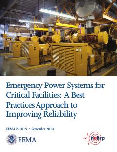
FEMA P-1019, Emergency Power Systems for Critical Facilities: A Best Practices Approach to Improving Reliability (September 2014)
At critical-facility data centers, place generators, ATS, fuel tanks and pumps above the greatest of BFE + 3 ft, DFE + 1 ft and 500-year elevation + 1 ft, and prefer elevation to dry floodproofing.
- Generators over 300 kW are almost exclusively diesel-fueled.
Headquarters, Department of the Army (U.S. Army Corps of Engineers PREP) 2006
TM 5-698-5 Survey of Reliability and Availability Information for Power Distribution, Power Generation, and Heating, Ventilating and Air Conditioning (HVAC) Components for Commercial, Industrial, and Utility Installations (22 July 2006)
When modelling the power and cooling chain use these values as starting failure rates and MTBF/MTTR inputs and convert them into availability with the method of TM 5-698-1.
- Diesel engine generators overall: 0.528 failures/yr, MTBF about 16,590 h, MTTR 24.22 h, operational availability 0.99399.
Consulting-Specifying Engineer 2026
Know the electrical, power components in a data center
Seed facility-type templates with default UPS/generator redundancy and fuel autonomy from Table 1.
- Generators should be loaded to at least 30% to avoid wet stacking.
Uptime Institute 2026
Uptime Institute Annual Outage Analysis 2026 (8th annual) — press release (with 2025 findings)
Weight UPS, ATS/STS and generator failure modes highest in the reliability model
- About 1 in 10 outages has serious or severe impact