
4 Steps to Reducing Bypass Airflow
Upsite Technologies blog · Lars Strong
Upsite blog post that redefines bypass airflow as any cooling airflow in excess of IT airflow and proposes an ordered improvement method.
On this page
Overview
Strong's 2014 post defines bypass airflow as any cooling airflow in excess of IT airflow, not just leakage through holes. The core finding is that sealing cable openings and managing perforated tiles does not reduce total airflow volume; it merely relocates bypass to the cold aisle. The post is a freely available blog entry.
The method starts by measuring the cooling capacity factor (CCF): the rated capacity of running cooling units (kW) divided by 1.10 times the IT critical load (kW), the extra 10% covering lights, people and similar loads. With fixed-speed or full-speed fans, CCF approximates the room's bypass airflow ratio. Airflow management is then improved in order: raised floor, rack (blanking, under-cabinet and rail gaps) and row (gaps, empty positions, containment).
Finally return set points are raised up to the IT inlet maximum, and units are switched off or fan speed is reduced via VFDs, keeping redundant units running. The process is iterated. The post is a practitioner's view, and CCF should be remembered as an approximate indicator that does not replace detailed measurement and simulation.
Key points
- Bypass airflow is defined as any cooling airflow in excess of IT airflow.
- CCF = rated capacity of running cooling units (kW) / (1.10 x IT critical load kW); the 10% covers lights, people etc.
- With fixed-speed or full-speed fans, CCF approximates the room's bypass airflow ratio.
- Sealing cable openings and managing perforated tiles moves bypass to the cold aisle rather than reducing total volume.
- Improve airflow management in order: raised floor, rack (blanking, under-cabinet and rail gaps), row (gaps, empty positions, containment).
- Then raise return set points up to the IT inlet maximum, switch off units or reduce fan speed via VFDs, keeping redundant units running.
- The method is iterative.
Using it in design
- Compute CCF for each room from running cooling capacity and IT load and show it as a KPI, with a warning when it is high (oversupply).
- In the efficiency wizard, use a design checklist that enforces floor, rack and row sealing items before allowing set-point increases.
- Verify that redundancy is kept when set points are raised.
Monthly newsletter · free
Keep your reading list current
Once a month: new library sources, changes to Turkish regulations and upcoming data centre events.
SoSo CAD
Check cooling capacity alongside your design
Review zone heat loads, available capacity and the capacity balance after the largest unit is lost in SoSo CAD.
Request a demo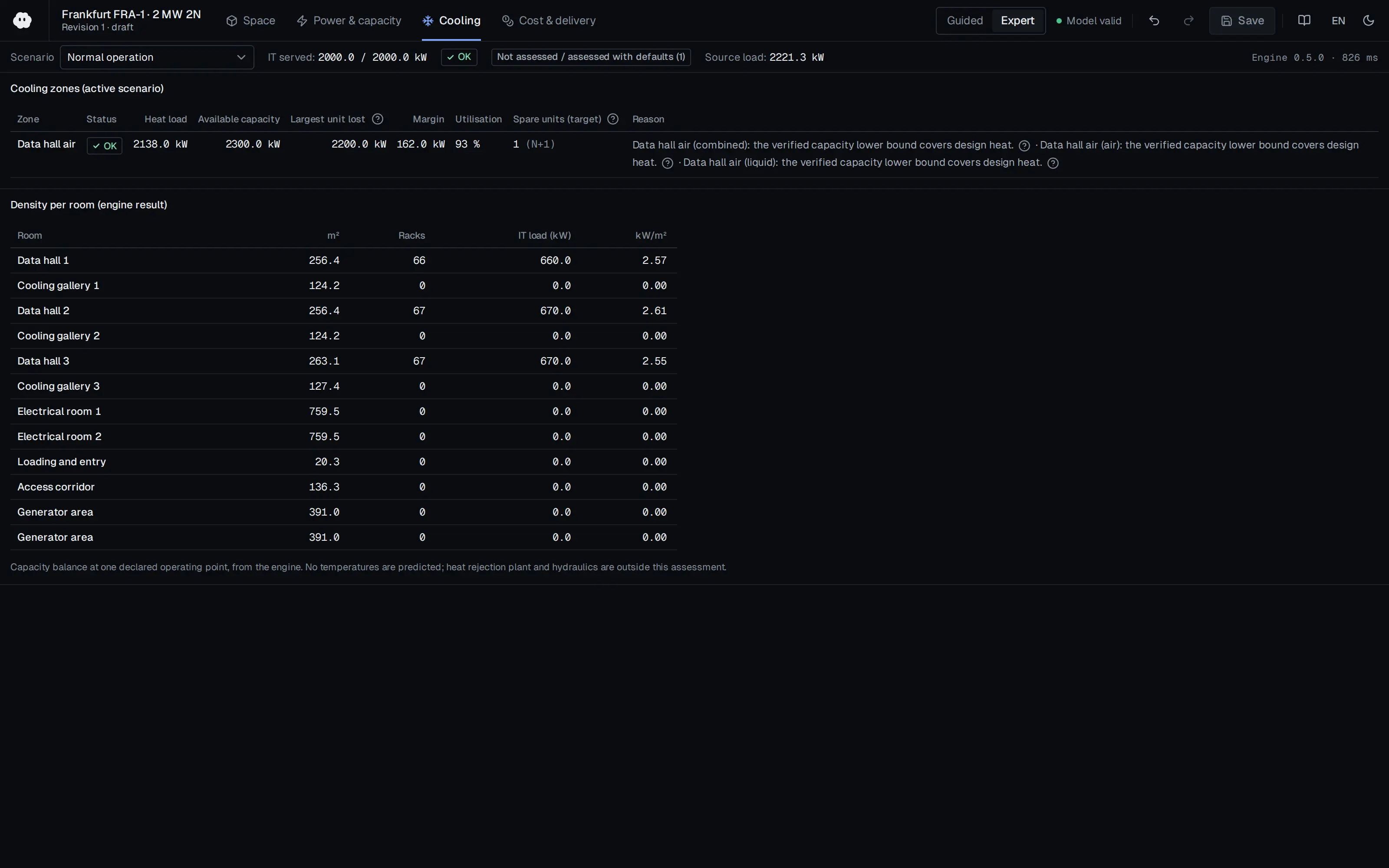
Who should read it
Operations and design engineers who want to improve cooling efficiency in air-cooled halls.
Publication details
- Authors
- Lars Strong
- Publisher
- Upsite Technologies blog
- Year
- 2014
- Document language
- English
- Source type
- Manufacturer
- Access
- Free to read
- Licence
- Copyright retained; citation only — the publisher’s terms apply to the original document
Citation
Lars Strong (2014). 4 Steps to Reducing Bypass Airflow. Upsite Technologies blog. https://www.upsite.com/blog/4-steps-reducing-bypass-airflow/
Events on this subject
Browse the events calendarAll content and rights belong to the respective authors and publishers. SoSo CAD provides only the citation, its own summary and a link to the source, and is not responsible for the sources' content.
Related sources
All sources on this topic
Buildings (MDPI AG) 2026
Thermal Environment Assessment for Energy-Efficient Cooling in Air-Cooled Data Centers: Measurement, CFD, and Predictive Models
In a design tool, set CFD accuracy expectations from this review's ranges (0.1-4 °C absolute, relative mostly below 20%) and do not limit validation scope to temperature; ask for velocity and pressure too.
- Of the 58 CFD studies, Fluent was used in 24 (41.4%) and 6SigmaDC in 12; standard k-epsilon in 41 (about 70.7%).
Applied Sciences (MDPI AG) 2025
Optimization of Airflow Organization in Bidirectional Air Supply Data Centers in China
In retrofitting an existing raised-floor hall, first close unused rack spaces with blanking panels (alone they cut SHI by 42.61%); containment alone gave little benefit.
- Baseline RTI 0.786, SHI 0.230, RCI-HI 0.992. Blanking alone: SHI 0.132, RCI-HI 1. Blanking plus full CAC (Case 7): RTI 1, SHI 0.027.
Scientific Reports (Springer Science and Business Media LLC) 2025
Energy efficiency enhancement in two European data centers through CFD modeling
Set up the retrofit workflow as KPI-guided: with a validated CFD model compute RCI, RHI, RTI and the recirculation index, then test rack repositioning, separators, sealing unused bays and removing badly placed ventilation units in sequence.
- KPI limits: ASHRAE recommended 18-27 °C and allowable 15-32 °C inlet temperatures.
European Commission JRC 2025
2025 Best Practice Guidelines for the EU Code of Conduct on Data Centre Energy Efficiency (JRC141521, EUR 40267)
Design the facility to operate within the ASHRAE Class A2 allowable range and require A2 operation within warranty in IT procurement; plan separate environmental zones (practice 5.3.4) for legacy equipment.
- IT equipment AC/DC power converters should be rated at 90% efficiency or better across expected load ranges.
Frontiers in Built Environment (Frontiers Media SA) 2024
Effects and optimization of airflow on the thermal environment in a data center
Make aisle containment the default in raised-floor or in-row cooling: containment raised ASE from 65.69% to 85.57-90.25% and brought SHI close to zero.
- Without containment, cabinet No. 19 had a mean inlet temperature of 30.1 °C and a maximum of 36.7 °C, and ten cabinets went above the 27 °C limit.
U.S. DOE FEMP / NREL 2024
Best Practices Guide for Energy-Efficient Data Center Design (Revised July 2024)
Weigh the supply air setpoint against server fan energy: raise it in small steps within the ASHRAE recommended range so the most demanding inlet nears 80 °F, only after air management is in place, and control to IT inlet temperature rather than return temperature.
- Compute racks reached 60 kW in 2013, and recent liquid-cooled racks exceed 125 kW.