
Deploying Liquid Cooling in the Data Center: A Guide to High-Density Cooling (1 MW IT load)
Vertiv
A practical guide that walks through converting a 1 MW IT load to hybrid liquid/air cooling, with a worked example giving per-rack and cluster flow and heat split.
On this page
Overview
The guide's main example is 20 racks x 50 kW = 1 MW. Each rack sends 37.5 kW to liquid and 12.5 kW to air, which at cluster scale is 750 kW liquid and 250 kW air. Cold-plate flow is taken as about 1.5 L/min per kW (0.4 gpm/kW), giving 56.25 L/min for a 50 kW rack and 1,125 L/min for the cluster. A reader can thus turn a ratio like "75% liquid" straight into pipe and pump flow.
Technology choice is tied to rack density: passive rear doors suit roughly 5-25 kW racks and active rear doors 50-70 kW, while direct-to-chip is treated for higher densities. The newest AI servers are noted as approaching 6-10 kW TDP each, which explains why 50 kW per rack is becoming ordinary.
CDU placement (in-rack, end-of-row, centralised) and redundancy get separate treatment. Row-level N+1 needs two CDUs, one on duty and one standby, which carries a floor-space cost. The filtration rule is clear: cold plates with 100 micron fin pitch need filtration no coarser than 50 microns. On the electrical side, the paper discusses what changes when 100 x 10 kW racks become 20 x 50 kW racks. The introduction rests on Uptime data: 17% of data centers already use liquid cooling and another 61% are considering it. The guide dates from 2023 and centres on one 1 MW example; at far higher densities (racks above 100 kW) these flows and ratios should be revalidated.
Key points
- Worked example: 20 racks x 50 kW = 1 MW; 37.5 kW/rack to liquid and 12.5 kW to air (750 / 250 kW cluster)
- Cold-plate flow ~1.5 L/min per kW; 56.25 L/min per 50 kW rack; 1,125 L/min cluster
- Passive rear doors suit ~5-25 kW racks; active rear doors 50-70 kW
- Cold plates with 100 micron fin pitch need filtration no coarser than 50 microns
- Row-level N+1 CDU redundancy requires two CDUs (one duty, one standby)
- Newest AI servers approach 6-10 kW TDP per server
- Survey: 17% of data centers already use liquid cooling; another 61% considering it
Using it in design
- Calculation default: DLC flow = 1.5 L/min per kW of liquid-captured heat; to adjust by dT use flow = P/(4.18 x dT) L/s.
- Default secondary-loop filtration to 50 micron.
- In the rear-door catalog apply thresholds: passive <= 25 kW, active <= 70 kW racks.
- For CDU redundancy, show the floor-space cost of row-level N+1 against a centralised CDU gallery.
Monthly newsletter · free
Keep your reading list current
Once a month: new library sources, changes to Turkish regulations and upcoming data centre events.
SoSo CAD
Check cooling capacity alongside your design
Review zone heat loads, available capacity and the capacity balance after the largest unit is lost in SoSo CAD.
Request a demo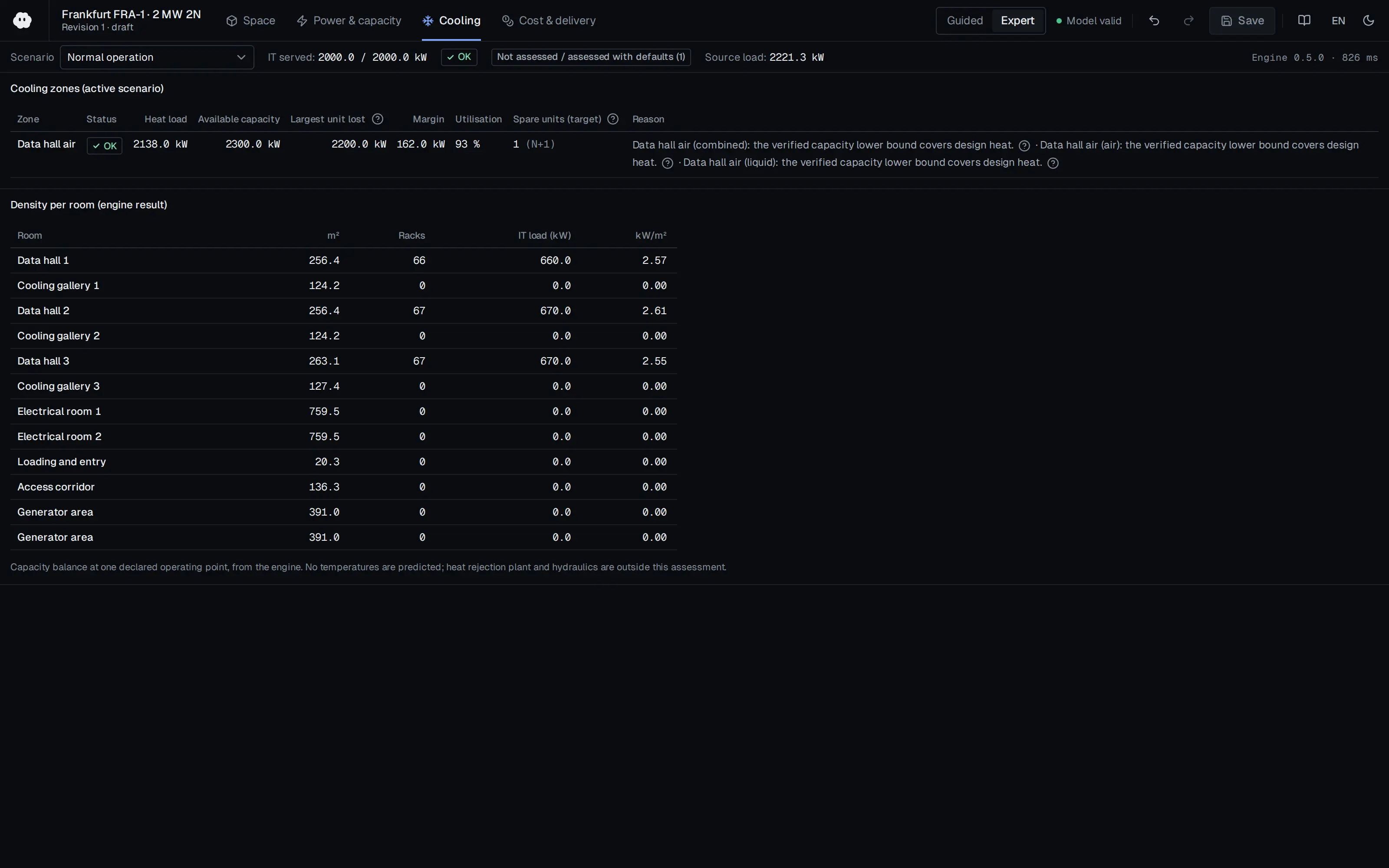
Who should read it
Facility and mechanical engineers converting an existing air-cooled hall to hybrid liquid cooling.
Related standards
- ASHRAE TC9.9 Liquid Cooling Guidelines
- OCP Advanced Cooling Solutions
Publication details
- Authors
- Vertiv
- Publisher
- Vertiv
- Year
- 2023
- Document language
- English
- Source type
- Manufacturer
- Access
- Free to read
- Licence
- Copyright retained; citation only — the publisher’s terms apply to the original document
Citation
Vertiv (2023). Deploying Liquid Cooling in the Data Center: A Guide to High-Density Cooling (1 MW IT load). Vertiv. https://prod.vertiv.cn/4a9616/globalassets/documents/white-papers/liquid-cooling/vertiv-liquidcooling-wp-en-na-sl-71113-web.pdf
Events on this subject
Browse the events calendarAll content and rights belong to the respective authors and publishers. SoSo CAD provides only the citation, its own summary and a link to the source, and is not responsible for the sources' content.