
Thermal Performance Evaluation of a Data Center Cooling System under Fault Conditions
Energies (MDPI AG) · Jinkyun Cho, Beungyong Park et al.
A case study of a 20 MW, nine-storey chilled-water CRAH data centre in Korea with cold-aisle containment and district cooling: after the central plant stops and UPS-backed pumps keep circulating, how long can the thermal capacity of the water in the pipes keep server inlets within ASHRAE limits?
CC BY 4.0 — share with attribution
On this page
Overview
The study asks how long server inlet temperature stays acceptable during a cooling system fault and how quickly backup cooling must be running. The 6SigmaDC room model has 192 racks at 4.0 kW with CAC, underfloor supply with side-wall return, a 900 mm raised floor, a 3.0 m false ceiling, 150 kW CRAHs and chilled water varied from 10 to 18 °C. The model finds the highest chilled-water and CRAH supply temperatures that still give compliant inlets, and a pipe-volume energy balance then converts those temperatures into elapsed time after the outage.
Server inlets stayed within 18-27 °C up to a CRAH supply-air temperature of about 24 °C, corresponding to 17 °C chilled water. Above 17 °C chilled water, CRAH capacity falls below 80% and room temperature rises rapidly; from 18 °C chilled water and 25 °C supply air, coil capacity fell below the load and inlet temperatures rose rapidly. The chilled-water piping held 234.3 m³ in total, about 45 m³ per typical floor, serving a 2500 kW floor cooling load at 6.75 m³/min with a fixed 5.5 °C water delta-T.
After the outage, chilled water took about 150 s to rise from 10 to 14 °C, and the whole 45 m³ reached 15.5 °C at 3.45 min, 21.0 °C at 10.36 min and 26.5 °C at 17.27 min. Compliant operation could continue for about 320 s (5 min 20 s) after the cooling outage, with CRAH coil capacity at 85%, so backup cooling must be active within 300 s. High-temperature, contained designs have only about five minutes before backup cooling must be running.
Limits: a single project (20 MW, Korea) and six fault conditions; the result depends on this plant's pipe volume, CRAH capacity and 4 kW per rack load. The authors also address organising and managing operational stability and energy-efficiency verification systematically through the commissioning process.
Key points
- CFD module: 192 racks at 4.0 kW/rack with CAC, underfloor supply with side-wall return, 900 mm raised floor, 3.0 m false ceiling, 150 kW CRAHs and chilled water from 10 to 18 °C.
- Server inlets stayed within 18-27 °C up to a CRAH supply-air temperature of about 24 °C, corresponding to 17 °C chilled water; above that CRAH capacity falls below 80% and room temperature rises rapidly.
- The chilled-water piping held 234.3 m³ in total, about 45 m³ per typical floor, serving a 2500 kW floor cooling load at 6.75 m³/min with a fixed 5.5 °C delta-T.
- After the outage, water took about 150 s to rise from 10 to 14 °C; the 45 m³ reached 15.5 °C at 3.45 min, 21.0 °C at 10.36 min and 26.5 °C at 17.27 min.
- Compliant operation could continue for about 320 s (5 min 20 s) after the outage with CRAH coil capacity at 85%, so backup cooling must be active within 300 s.
- From 18 °C chilled water and 25 °C supply air, coil capacity fell below the load and inlet temperatures rose rapidly.
Using it in design
- Calculate the permissible time for a cooling outage with a pipe-volume energy balance and set the backup-cooling start time accordingly (here 300 s); high-temperature, contained designs give less time.
- Limit chilled-water and CRAH supply temperature to the ASHRAE-compliant upper bound (17 °C water, 24 °C air) as the pre-fault operating point; above 17 °C capacity falls below 80%.
- Model UPS-backed pumps and pipe volume (45 m³ per typical floor) as thermal buffer and add them to fault-condition commissioning test scenarios.
Monthly newsletter · free
Keep your reading list current
Once a month: new library sources, changes to Turkish regulations and upcoming data centre events.
SoSo CAD
Check cooling capacity alongside your design
Review zone heat loads, available capacity and the capacity balance after the largest unit is lost in SoSo CAD.
Request a demo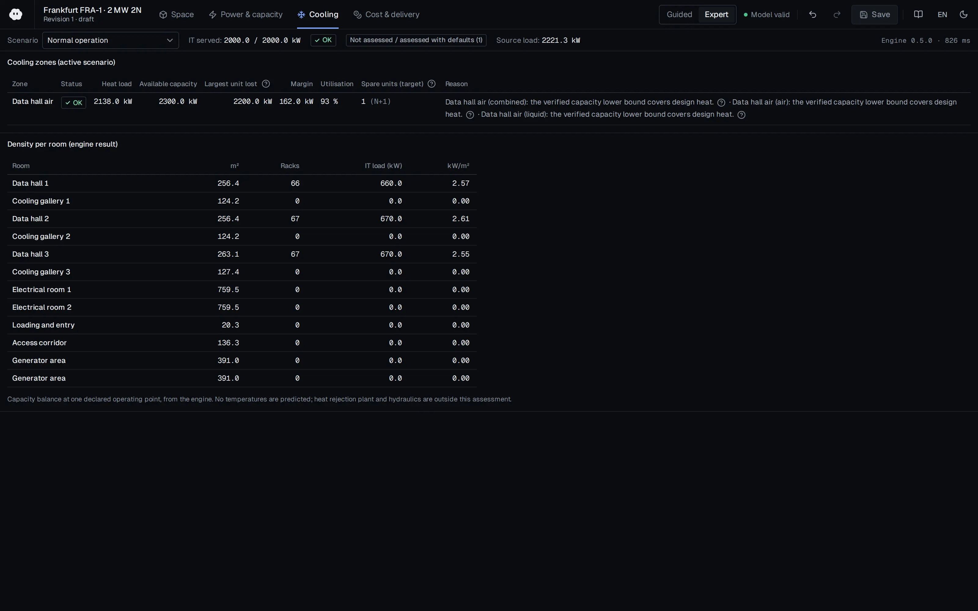
Who should read it
Designers and commissioning engineers determining cooling fault resilience and backup-cooling start time.
Document contents
- 1. Introduction
- 2. Literature Reviews
- 3. Major Issues in Data Center Planning (3.1 Root Causes and Scale of Fault Conditions, 3.2 Temperature and IT Reliability)
- 4. Case Study: Data Center and Modeling (4.1 Data Center Cooling System, 4.2 IT Server Room Thermal Model, 4.3 Simulation)
- 5. Temperature Control Approaches (5.1 Temperature Increase over Time After a Cooling System Outage)
- 6. Conclusions
Related standards
- ASHRAE TC 9.9 Thermal Guidelines for Data Processing Environments
- Uptime Institute Tier Standard
Read the document
dc-cooling-outage-fault-conditions-2019.pdf
CC BY 4.0 — share with attribution
The document is provided unaltered because its licence permits redistribution.
Publication details
- Authors
- Jinkyun Cho; Beungyong Park; Yongdae Jeong
- Publisher
- Energies (MDPI AG)
- Year
- 2019
- Volume
- 12
- Issue
- 15
- Pages
- 2996
- Document language
- English
- Source type
- Scientific
- Access
- Open licence — downloadable
- Licence
- CC BY 4.0 — share with attribution
- Licence evidence
- www.mdpi.com
Original licence note
PDF p.1: open access article distributed under the terms and conditions of the Creative Commons Attribution (CC BY) license.
Citation
Jinkyun Cho; Beungyong Park; Yongdae Jeong (2019). Thermal Performance Evaluation of a Data Center Cooling System under Fault Conditions. Energies (MDPI AG). 12(15), 2996. https://doi.org/10.3390/en12152996
Events on this subject
Browse the events calendarAll content and rights belong to the respective authors and publishers. SoSo CAD provides only the citation, its own summary and a link to the source, and is not responsible for the sources' content.
Related sources
All sources on this topic
Energies (MDPI AG) 2020
A Comparative CFD Study of Two Air Distribution Systems with Hot Aisle Containment in High-Density Data Centers
In high-density HAC halls, prefer a raised floor to hard-floor supply; on a hard floor high-velocity jets can starve the racks nearest the CRAHs and draw hot air back into them.
- On the hard floor, supply velocities of 10 m/s or more persisted to the eighth rack position, versus the fourth with a raised floor.
Journal of Engineering Research and Sciences (Journal of Engineering Research and Sciences) 2026
CFD Analysis of Data Center Hall Cooling Performance under Normal and Failure Modes with Control Strategies and Airflow Leakages
Do thermal verification of failure mode (two ACUs offline) with realistic air leakage (cabinet gaps, HAC panel joints); a leak-free model can comply while the leaky model exceeds 32 °C.
- The grid study selected 7,288,454 cells with the standard k-epsilon model and wall functions.
Open Compute Project Foundation 2026
Whitepaper: Thermal Boundaries in AI Infrastructure - Matching cooling technologies to compute through the power inflection, Version 1.00 (October 2026)
Choose cooling architecture against target rack power and each method's usable envelope: a 45 kW air ceiling (60-80 kW with rear doors), 120-250 kW class cold-plate racks, and the paper's anchor values for announced 600 kW-class racks.
- Practical air-cooled rack ceiling is taken as 45 kW, extendable to about 60-80 kW with rear-door heat exchangers.
Open Compute Project Foundation 2025
Modular Technology Cooling System for "Cloud Scale": Design & Delivery of Liquid to Rack Distribution Systems, Version 1.0 (25 August 2025)
When sizing TCS capacity against electrical capacity, state the cold-plate capture fraction (70-80%) and target delta-T (10 or 20 C) explicitly, and use the roughly doubled delivery at 20 C (4,845 versus 2,422 kW) as design headroom.
- Most IT equipment is designed for a 10 C coolant delta-T, with some designs considering 20 C.
Open Compute Project Foundation 2024
Data Center Liquid Distribution Guidance & Reference Designs, Revision 1.0 (January 8, 2024)
Reserve space for tap-off valves, pipe paths with straight runs, valve and fitting replacement, drainage and condensation collection in the original design.
- Liquid above 50 °C (122 °F) is far better for heat reuse than 35 °C (95 °F) air, and improves ERE.
Schneider Electric 2025
Direct Liquid Cooling System Challenges in Data Centers
Use the eight challenges as a DLC readiness checklist in the commissioning and design-review module.
- Heat capture ratio defines the air share: 80% liquid capture leaves 20% for air cooling.