
High-Performance Computing Data Center Cooling System Energy Efficiency (ESIF)
National Laboratory of the Rockies (formerly NREL) · National Laboratory of the Rockies
This page walks through the ESIF HPC data center cooling system in schematic steps: liquid cooling via CDUs for most heat, fan walls for residual air-cooled load, a closed energy-recovery water loop and a hierarchy of heat rejection.
On this page
Overview
The source is a web page from the National Laboratory of the Rockies (formerly NREL) describing the cooling system of the ESIF high-performance computing (HPC) data center; it was last updated on 17 February 2026. The page is a schematic walk-through that explains each step of the system in order. The first principle of the system is that most of the heat is captured by liquid.
Operators require 90% or more of IT heat to be captured by liquid cooling, and fan walls handle the residual air-cooled load. Cooling distribution units (CDUs) supply coolant at the temperature, pressure and chemistry the IT needs. This shows that the liquid capture fraction can be a design target in liquid-cooled halls. A hierarchy is defined for heat rejection. Heat is first reused as building process hot water, then sent to a thermosyphon dry cooler and finally to cooling towers.
The system also includes a closed energy-recovery water loop. The ordering follows the logic of using the most efficient available option first, to reduce energy and water consumption. The source is a presentation of a single facility, which means it is the practice of one research facility rather than a general standard or calculation method. The 90% capture rate should therefore be read as this facility's operating requirement and not as a universal rule. The page gives no detailed capacity, flow or temperature values, so this record contains none either.
Key points
- Operators require 90% or more of IT heat to be captured by liquid cooling.
- Cooling distribution units supply coolant at the temperature, pressure and chemistry the IT needs.
- Fan walls handle the residual air-cooled load.
- A closed energy-recovery water loop is used.
- Heat rejection hierarchy: reuse as building process hot water, then thermosyphon dry cooler, then cooling towers.
- The page was last updated on 17 February 2026.
- The source describes one facility's practice; it is not a general standard.
Using it in design
- Model heat rejection as a priority chain (reuse, dry cooler, evaporative tower) with hourly switching.
- Allow a 'minimum liquid capture fraction' design parameter for liquid-cooled halls.
- Design the layout so the residual air-cooled load is met by fan walls or a similar solution.
- Keep temperature, pressure and chemistry requirements as catalog fields when selecting CDUs.
- Assess heat reuse by matching it to the building's process hot water demand.
Monthly newsletter · free
Keep your reading list current
Once a month: new library sources, changes to Turkish regulations and upcoming data centre events.
SoSo CAD
Check cooling capacity alongside your design
Review zone heat loads, available capacity and the capacity balance after the largest unit is lost in SoSo CAD.
Request a demo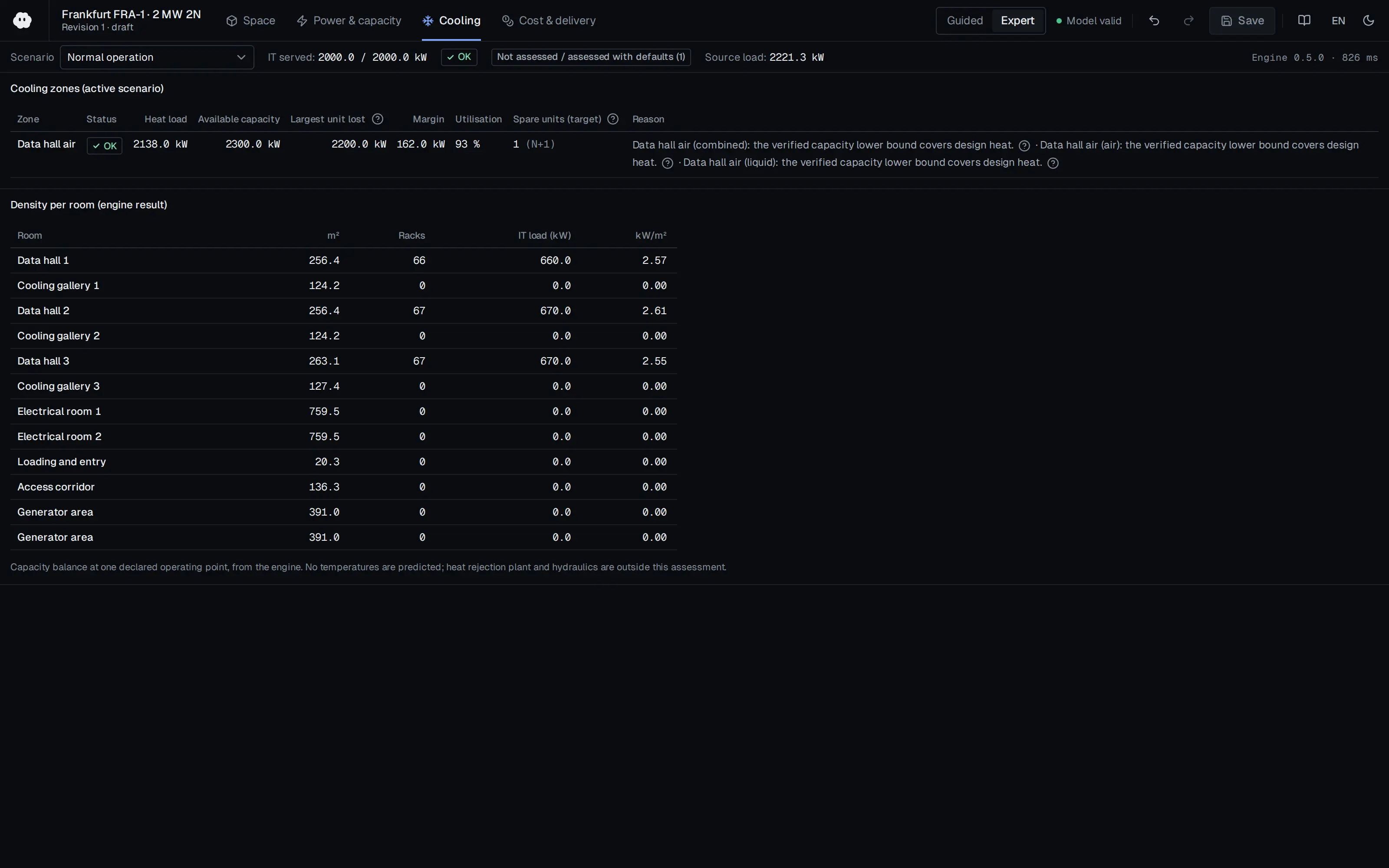
Who should read it
Mechanical engineers designing cooling and heat rejection for liquid-cooled, high-density HPC data centers.
Publication details
- Authors
- National Laboratory of the Rockies
- Publisher
- National Laboratory of the Rockies (formerly NREL)
- Year
- 2026
- Document language
- English
- Source type
- Government / public
- Access
- Free to read
- Licence
- Copyright retained; citation only — the publisher’s terms apply to the original document
Original licence note
NREL/NLR (contractor-operated DOE laboratory) web page; not US-Gov public domain. Cited only.
Citation
National Laboratory of the Rockies (2026). High-Performance Computing Data Center Cooling System Energy Efficiency (ESIF). National Laboratory of the Rockies (formerly NREL). https://www.nlr.gov/computational-science/data-center-cooling-system
Events on this subject
Browse the events calendarAll content and rights belong to the respective authors and publishers. SoSo CAD provides only the citation, its own summary and a link to the source, and is not responsible for the sources' content.
Related sources
All sources on this topic
Fluids (MDPI AG) 2026
A Review of Thermal Management in Modern Data Centres: Water Usage Effectiveness and Heat Transfer Coefficients
Set WUE targets from the heat-rejection topology (dry, free-cooling, hybrid, evaporative) and not only the server-side cooling technology; WUE depends on the share of heat rejected by evaporation.
- Dry facilities with closed-loop liquid cooling need essentially no water, while evaporative systems typically report WUE up to 2.5 L/kWh.
U.S. DOE FEMP / NREL 2019
Using Thermosyphon Hybrid Cooling System to Optimize Data Center Water Efficiency (DOE/GO-102019-5172, May 2019)
Arrange the heat-rejection hierarchy as in the scheme: heat reuse first, then dry cooling, evaporative towers last; write the control logic in that order.
- Installing the TSC required only a 1-day data center outage.
Schneider Electric 2026
Water Usage at AI Scale: Insights from a 100 MW Comparative Analysis
Compute and display WUE (L/kWh IT) next to PUE for every cooling design.
- Dallas WUE falls from 0.42 to 0.22 L/kWh; Paris from 0.12 to 0.06 L/kWh.
Burns & McDonnell 2024
Fluid Dynamics: Liquid Cooling's Role in the Future of Data Centers
For liquid-cooled racks, always keep a residual air-cooling load (default 20-50% of IT, user-adjustable) and size CRAH or fan-wall capacity for it.
- Some solutions reach 80-120+ kW per rack versus a typical 8-12 kW.
Microsoft 2024
Sustainable by design: Next-generation datacenters consume zero water for cooling
Add 'closed-loop DLC + dry cooler / air-cooled economizing chiller (zero-evaporation)' to the cooling-option catalog with WUE_cooling about 0.
- Pilots in Phoenix and Mt. Pleasant were planned for 2026.
Open Compute Project 2024
Data Center Liquid Distribution Guidance & Reference Designs, Rev 1.0 (OCP Advanced Cooling Facilities)
In the liquid-cooling calculator implement Q = m*cp*delta-T for TCS/FWS sizing (water cp 4.18 kJ/kg-K, PG25 option) and size pipes by maximum velocity.
- Q = volumetric flow x delta-T x density x specific heat; by volume water carries about 3,300 times the heat of air.