
Guidelines for Connection of Liquid Cooled Information Technology Equipment (ITE) to Data Center Facility Systems, Revision 1, Version 1.0 (April 2022)
Open Compute Project Foundation · Mitchell, D. (Victaulic), Menoche, J. (Vertiv) et al.
An OCP Advanced Cooling Facilities (ACF) white paper proposing standard practices for connecting vendor liquid cooling solutions (door heat exchanger, cold plate, immersion) to facility or condenser water systems, so that IT refresh does not need facility shutdowns.
CC BY-SA 4.0 — share with attribution under the same licence
On this page
Overview
The paper starts from the fact that technology refresh happens many times in a data centre's life and that liquid-cooled IT, in use for decades mainly for HPC and usually installed during initial construction, has been refreshed only with a limited set of solutions, often requiring a facility shutdown. High-density applications such as AI, VR and machine learning are making adding and changing liquid-cooled IT a standard operating requirement. The document describes ITE connecting to the facility water system (FWS) either directly or through a CDU that separates the technology cooling system (TCS) loop with a heat exchanger.
The fundamental connection components are: connection and isolation (reducing mean time to repair and improving concurrent maintainability), vent, drain and flush connections, strainers to keep contamination off heat exchanger coils, a flow balancing valve to stabilise pressure differential across the CDU or ITE, metering points for differential pressure and flow, and alignment accommodation. Some connection point requirements are taken from the OCP ACS Immersion document: FWS interfaces marked blue inlet and red outlet with flow arrows; operation from 50 kPa absolute (partial vacuum) to 800 kPa gauge; support for water and glycol mixtures up to 50%; and connection to overhead or underfloor distribution.
Pipe connection size is the key parameter setting the future kW capacity of liquid-cooled ITE. Heat transfer follows Q = volumetric flow x delta T x specific heat capacity, and Table 1 gives maximum practical cooling by pipe size and fluid temperature rise; flow velocity affects energy, diameter affects construction and delta T affects both the cooling system and ITE performance. Rack-based solutions (door HX, cold plate, rack-based immersion) are typically 0.75 inch/DN20 to 1.25 inch/DN40 with threaded connections, and the paper recommends BSPP as the global thread standard. CDU and tank connections of 2 inch/DN50 and above use grooved couplings (ASTM F1476) or flanges.
Choosing among connection types is risk-based. Above 1.25 inch, quick disconnects become hard to operate at FWS pressures because of hydrostatic thrust, and no global non-proprietary quick disconnect standard exists, so isolation valves upstream of quick disconnects are strongly recommended. For pipes of 2 inch and above, grooved couplings are favoured over Class 150 flanges because they need no hot work, tolerate pipe movement and misalignment, and carry load in the groove rather than the bolts; mission critical grooved couplings are expected to have housing and gasket from one manufacturer, traceable marking and certified, auditable installation verification. Hoses are maintenance items, with 10 years the general industry guidance for mission critical hose.
The paper also covers condensation and risk: keeping FWS liquid above dew point reduces condensation risk, and the ASHRAE recommended dew point limit for air-cooled classes A1-A4 is 15 C. Connection points should be assessed with failure mode and effects analysis (FMEA) to reduce severity, probability and detectability; connection methods that cannot be verified should not be used in high-severity locations or should be protected by leak detection. Welded, fused and crimped joints give no reconnection capability, so threaded, grooved and flanged connections are the focus for ITE refresh. The paper is advisory: identifying exceptions to the pressure range is the facility owner's responsibility and final validation requires a licensed engineer.
Key points
- FWS interfaces must be marked: inlet blue, outlet red, each with a flow direction arrow.
- Connections should support FWS from 50 kPa absolute (partial vacuum) to 800 kPa gauge, water or glycol mixtures up to 50%, with filtration and water quality per ASHRAE TC 9.9.
- Pipe connection size sets future kW capacity: Q = volumetric flow x delta T x specific heat; a table gives maximum practical cooling by pipe size and temperature rise.
- Rack-based solutions are typically 0.75 inch/DN20, 1 inch/DN25 or 1.25 inch/DN40 with threaded connections; the paper recommends BSPP as the global thread standard.
- Isolation valves upstream of quick disconnects are strongly recommended because hydrostatic thrust makes operation difficult at FWS pressures and there is no global non-proprietary standard.
- For pipe sizes of 2 inch/DN50 and larger, grooved couplings (ASTM F1476) are favoured over Class 150 flanges for no hot work and tolerance to pipe movement.
- Keeping FWS liquid above dew point avoids condensation; the ASHRAE recommended dew point limit for air-cooled classes A1-A4 is 15 C.
- Each connection should include isolation, vent/drain/flush connections (so flushing bypasses strainers and HX), strainers and flow balancing valves.
- Flange gaskets can relax 20-50% of thickness in the first 4-6 hours; torque should be verified at installation and again at least 4 hours later.
- Hoses and alignment devices typically last under 20 years and are maintenance items; general guidance for mission critical hose is 10 years.
Using it in design
- Place standard tap-off points with isolation valves, vent/drain/flush connections and strainers at every rack or CDU connection in liquid cooling layouts, sized from Q = flow x delta T x cp so future kW per position is explicit.
- Add validation rules: FWS design pressure within 50 kPa abs to 800 kPa g, glycol at or below 50%, and a warning when supply temperature is at or below room dew point (15 C default).
- Colour-code supply and return in drawings and BIM exports (blue inlet, red outlet).
- For rack connections under 2 inch specify BSPP threaded connection points and place an isolation valve upstream of any quick disconnect; for CDU and tank connections of 2 inch and above choose grooved coupling or flange by movement, alignment and hot work needs.
- Run an FMEA on connection points; prefer verifiable methods (radiography or visual inspection plus pressure test) in high-severity locations and plan leak detection and drip trays elsewhere.
- Put components with warranties under 20 years (hoses, strainers, valves, flanges, movement devices) in the maintenance schedule and in low-risk locations.
Monthly newsletter · free
Keep your reading list current
Once a month: new library sources, changes to Turkish regulations and upcoming data centre events.
SoSo CAD
Check cooling capacity alongside your design
Review zone heat loads, available capacity and the capacity balance after the largest unit is lost in SoSo CAD.
Request a demo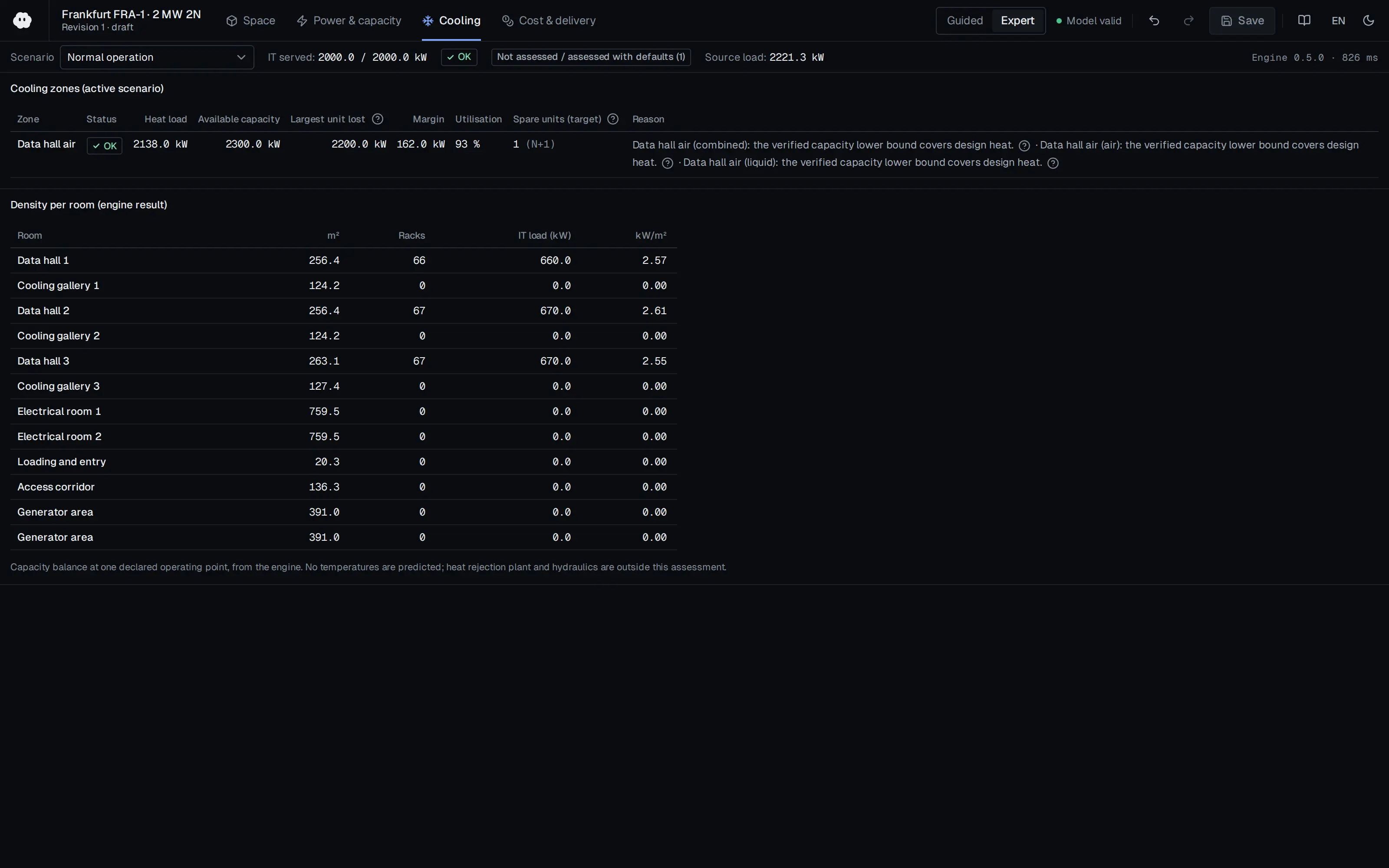
Who should read it
Cooling designers, mechanical contractors, CDU and cooling solution manufacturers and operations teams connecting liquid-cooled IT to facility water systems.
Document contents
- Executive Summary
- Definitions
- Introduction
- Design Considerations - Adding Liquid Cooled ITE
- ITE Connection Point Standardization
- ITE Thread Connections
- Quick Disconnects
- Grooved Coupling Connections
- Flange Connections
- Alignment Considerations
- Flexible Hose
- Dew point
- FMEA Analysis to Reduce Liquid Cooled ITE Connection Risk
- Key Components / Functions of Connection Lines
- Conclusion
- Appendix A: Connection/Disconnection Considerations (threaded, grooved couplings, flange joints)
- Appendix B: Fixed Connection Methods - Welds, Fusion, Crimped
Related standards
- ASHRAE TC 9.9 Liquid Cooling Guidelines
- ASTM F1476
- ASME B16.5 Class 150 flanges
- OCP ACS Immersion Requirements Rev 2
Read the document
ocp-acf-connection-guidance.pdf
CC BY-SA 4.0 — share with attribution under the same licence
The document is provided unaltered because its licence permits redistribution.
Publication details
- Authors
- Mitchell, D. (Victaulic); Menoche, J. (Vertiv); Gross, J. (JMGross Engineers); Sorell, V. (Microsoft); Musilli, J. (CPS/Integra)
- Publisher
- Open Compute Project Foundation
- Year
- 2022
- Document number
- Rev 1 v1.0
- Document language
- English
- Source type
- Industry body
- Access
- Open licence — downloadable
- Licence
- CC BY-SA 4.0 — share with attribution under the same licence
- Licence evidence
- www.opencompute.org
Original licence note
Page 29 states the work is licensed under the Creative Commons Attribution-ShareAlike 4.0 International License.
Citation
Mitchell, D. (Victaulic); Menoche, J. (Vertiv); Gross, J. (JMGross Engineers); Sorell, V. (Microsoft); Musilli, J. (CPS/Integra) (2022). Guidelines for Connection of Liquid Cooled Information Technology Equipment (ITE) to Data Center Facility Systems, Revision 1, Version 1.0 (April 2022). Open Compute Project Foundation. Rev 1 v1.0. https://www.opencompute.org/documents/ocp-acs-connection-guidance-acf-wp-05032022-pdf/
Events on this subject
Browse the events calendarAll content and rights belong to the respective authors and publishers. SoSo CAD provides only the citation, its own summary and a link to the source, and is not responsible for the sources' content.
Related sources
All sources on this topic
Open Compute Project Foundation 2026
Whitepaper: Thermal Boundaries in AI Infrastructure - Matching cooling technologies to compute through the power inflection, Version 1.00 (October 2026)
Choose cooling architecture against target rack power and each method's usable envelope: a 45 kW air ceiling (60-80 kW with rear doors), 120-250 kW class cold-plate racks, and the paper's anchor values for announced 600 kW-class racks.
- Practical air-cooled rack ceiling is taken as 45 kW, extendable to about 60-80 kW with rear-door heat exchangers.
Open Compute Project Foundation 2025
Modular Technology Cooling System for "Cloud Scale": Design & Delivery of Liquid to Rack Distribution Systems, Version 1.0 (25 August 2025)
When sizing TCS capacity against electrical capacity, state the cold-plate capture fraction (70-80%) and target delta-T (10 or 20 C) explicitly, and use the roughly doubled delivery at 20 C (4,845 versus 2,422 kW) as design headroom.
- Most IT equipment is designed for a 10 C coolant delta-T, with some designs considering 20 C.
Open Compute Project Foundation 2024
Data Center Liquid Distribution Guidance & Reference Designs, Revision 1.0 (January 8, 2024)
Reserve space for tap-off valves, pipe paths with straight runs, valve and fitting replacement, drainage and condensation collection in the original design.
- Liquid above 50 °C (122 °F) is far better for heat reuse than 35 °C (95 °F) air, and improves ERE.
Open Compute Project Foundation 2023
Cold Plate Cooling Loop Requirements, Rev 2
Require each vendor to fill in the parameters of importance tables for cold plates, hoses, quick disconnects, loops, manifolds and CDUs so offers can be compared.
- Glycol at 25% or above prevents bacterial growth; dielectric fluids are insulating but cost more and have higher GWP.

Open Compute Project Foundation 2023
Immersion Requirements Rev 2.0, First Amended (Revision 2.10, August 18, 2023)
Compare vendor offers on the same template: request W32 footprint density (kW/m2), full-solution static floor load, ceiling clearance and non-IT power per kW of IT in writing.
- Containment must hold at least 100% of the fluid volume of any single system without breach.

Open Compute Project Foundation 2020
Design Guidelines for Immersion-Cooled IT Equipment, Revision 1.0 (December 2020)
Compare the bill of materials of a server to be immersed (cable jackets, heat-shrink, EPDM capacitors, CMOS battery, relays, thermal paste) against the paper's problem table and obtain a compatibility statement from the fluid supplier for each item.
- In Soxhlet extraction testing, a mass loss below 2% indicates good material compatibility; the 48-hour test gives worst-case results.