
UFC 3-550-01 Exterior Electrical Power Distribution (1 September 2016, Change 3, 01 November 2019)
U.S. DoD (UFC) · Naval Facilities Engineering Command (NAVFAC), U.S. Army Corps of Engineers (USACE) et al.
DoD criteria for site-level medium-voltage distribution: transformers, switchgear, overhead lines, ductbanks, manholes, grounding and directional boring. It gives a data centre designer a numeric benchmark for the run from utility entry to the building.
U.S. public domain — U.S. Government work; free to reuse
On this page
Overview
This document belongs to the Unified Facilities Criteria (UFC) series prepared by NAVFAC, USACE and AFCEC and sets out how exterior electrical distribution is to be designed at military installations. It is read together with NFPA 70 and IEEE C2: it does not replace them, it adds DoD-specific requirements on top. The 2016 edition supersedes the 3 February 2010 version (including Change 1 of July 2012). The text described here is updated through Change 3 (1 November 2019), which added environmental severity classification, humidity design requirements and corrosion-prevention rules.
Chapter 1 covers purpose and exclusions and Chapter 2 covers power requirements. Chapter 2 rests on two principles: primary voltage is selected from NEMA C84.1, and primary distribution equipment is designed with future periodic maintenance as a principal consideration. Looped and alternate feeds are described as essential so that equipment can be taken out of service while limiting outage time for affected facilities. New primary systems are four-wire, multi-grounded and wye-connected at the source transformer.
Chapter 3 proceeds equipment by equipment: primary and secondary unit substations, pad-mounted distribution transformers, medium-voltage switchgear, pad-mounted switches, capacitors, overhead lines and underground systems. The underground section is the most detailed, defining ductbank sizes, burial depths, spare-duct ratios, manhole dimensions, equipment prohibited in manholes and the circumstances in which directional boring may be used. Appendix B treats directional boring and Appendix C gives best practices for general electrical power requirements.
The limits are clear. The document is not data centre specific, it assumes military-installation infrastructure (airfields, ordnance facilities, piers) and it lists separate exceptions for the Air Force and the Navy. The Navy, for example, requires SF6 or high-fire-point liquid insulated switchgear and EPR-insulated MV cable, while the Air Force bans T and Y splices on all medium-voltage systems. A data centre designer should treat the figures as a numeric reference point and not as a substitute for the utility operator's requirements or local standards.
Key points
- Pad-mounted transformers are not used above 3,000 A secondary current; units above 1,000 kVA at 208Y/120 V or above 2,500 kVA at 480Y/277 V must be built as secondary unit substations.
- Three-phase pad-mounted transformers must be loop-feed capable with 6 bushings; three switches are provided if a loop is possible and a single on-off switch for the end of a radial.
- If the 208Y/120 V dry-type load exceeds 40 percent of the 480 V service transformer capability, two liquid-filled transformers replace one 480Y/277 V service; double transformations are to be minimised and equipment connected at the highest available voltage.
- Elbow-type arresters go at the ends of all radials and at normally open loop points, for all voltages above 5 kV.
- Primary conduits are at least 5 in (127 mm), secondary (LV) conduits at least 4 in (103 mm) for conductors of 500 kcmil and larger; concrete encasement is at least 3 in (75 mm), burial at least 18 in (450 mm), and 24 in (600 mm) under roads and for 22-40 kV.
- On primary circuits at least one third of the ductbank must be empty spare conduits (and at least one conduit), and all spares get pull wires.
- Power manholes are at least 6.5 ft (2 m) deep and at least 9 ft by 12 ft (2.8 m by 3.7 m) inside for circuits above 15 kV; covers are designed for H20 highway loading. Transformers, switches, load junctions and separable (bolt-T) splices are prohibited inside manholes.
- Directional boring is permitted only for named crossings (roads, parking lots, water, approved sensitive areas), must not be chosen on cost alone, and is prohibited above 34.5 kV; medium voltage is defined as 1,000 V to 34.5 kV.
- Ground rods are at least 10 ft (3.0 m) long and 3/4 in (17 mm) in diameter, with below-grade connections by exothermic weld or hydraulic compression; systems not classified as multi-grounded need a 4/0 bare copper ring with at least four rods.
Using it in design
- Settle the loop or alternate-feed arrangement and the maintenance isolation points for the MV run from utility entry to the building early; the text treats shortening maintenance outages as a direct design driver.
- Check transformer selection against the 3,000 A secondary limit and the 1,000 kVA (208Y/120 V) and 2,500 kVA (480Y/277 V) thresholds; for larger data hall loads consider secondary unit substations or several transformers.
- In ductbank design verify the spare-conduit share (at least one third), the 3 in (75 mm) spacing between conduits, concrete cover and burial depth together with the corresponding ampacity derating.
- Place manholes at every splice and direction change and within 100 ft (30 m) of each riser pole, pad-mounted transformer or unit substation, keeping straight-run spacing to 400 ft (120 m), or 600 ft (180 m) where justified.
- For site grounding, add to the checklist the 10 ft (3 m) clear working space in front of pad-mounted gear, bollards where vehicles can strike equipment, and bonding of metal bollards within 8 ft to the ground ring.
- Note that oil-filled transformer siting points to UFC 3-600-01 and corrosive or humid locations point to UFC 3-501-01; read those dependent documents separately.
Monthly newsletter · free
Keep your reading list current
Once a month: new library sources, changes to Turkish regulations and upcoming data centre events.
SoSo CAD
Review your power design in SoSo CAD
Inspect supply paths, equipment loads and UPS failure scenarios in one model.
Request a demo
Who should read it
Electrical engineers and project managers designing medium-voltage site distribution, transformers and ductbanks for a data centre.
Document contents
- Chapter 1 General
- Chapter 2 Electrical Power Requirements: selection of primary voltage, design for maintenance
- 3-1 Main and Utilization Electric Supply Stations
- 3-2 General Electrical Requirements
- 3-3 / 3-4 Primary and Secondary Unit Substations
- 3-5 Pad-Mounted Distribution Transformers
- 3-6 / 3-7 Medium Voltage Switchgear and Pad-Mounted Switchgear
- 3-9 Capacitors
- 3-10 Overhead Power Distribution
- 3-11 Underground Electrical Systems: ductbanks, directional boring, manholes, MV cable
- 3-14 Distribution System Grounding
- 3-18 / 3-19 Environmental and Fire Protection Considerations
- Appendix A References
- Appendix B Directional Boring
- Appendix C Best Practices: General Electrical Power Requirements
- Appendix D Glossary
Read the document
ufc-3-550-01-exterior-power.pdf
U.S. public domain — U.S. Government work; free to reuse
The document is provided unaltered because its licence permits redistribution.
Publication details
- Authors
- Naval Facilities Engineering Command (NAVFAC); U.S. Army Corps of Engineers (USACE); Air Force Civil Engineer Center (AFCEC)
- Publisher
- U.S. DoD (UFC)
- Year
- 2019
- Document language
- English
- Source type
- Government / public
- Access
- Open licence — downloadable
- Licence
- U.S. public domain — U.S. Government work; free to reuse
- Licence evidence
- www.copyright.gov
Original licence note
DoD/USACE criteria marked "Approved for public release; distribution unlimited"; work of the U.S. Government (17 U.S.C. 105). Any third-party copyrighted material incorporated is identified at its point of use and is not covered.
Citation
Naval Facilities Engineering Command (NAVFAC); U.S. Army Corps of Engineers (USACE); Air Force Civil Engineer Center (AFCEC) (2019). UFC 3-550-01 Exterior Electrical Power Distribution (1 September 2016, Change 3, 01 November 2019). U.S. DoD (UFC). https://www.wbdg.org/FFC/DOD/UFC/ufc_3_550_01_2016_c3.pdf
Events on this subject
Browse the events calendarAll content and rights belong to the respective authors and publishers. SoSo CAD provides only the citation, its own summary and a link to the source, and is not responsible for the sources' content.
Related sources
All sources on this topic
CIGRE US National Committee, 2026 Grid of the Future Symposium (arXiv preprint) 2026
Comparative Analysis of Large Load Interconnection Requirements Across U.S. Transmission Entities
Design data-centre UPS and load control to the most restrictive entity's requirement: 6.0 s ride-through at 0.70-0.90 pu (CAISO), six fault-clearing attempts within 90 s (SPP), six 50-70 ms reclosings (Dominion), and the ban on constant-power control (SPP).
- MISO's proposal requires withstanding three voltage disturbances within 10 s and phase-angle jumps up to 25 degrees.
Open Compute Project Foundation 2026
Interface Specification Between Hyperscalers and Utility Grid for Disturbance Performance (Version 1.0.0)
For a new site, write the POI LVRT/HVRT envelope and the PFAPR requirement (90% within 2 s) as design criteria, and settle which voltage measurement (line-to-neutral or line-to-line) governs during protection coordination with the utility.
- In ERCOT NOGRR 282, cooling load is subtracted from the pre-fault load used to judge PFAPR.
arXiv preprint (Black & Veatch / University of Central Missouri) 2025
Enhancing Grid Resilience for Giga-Watt Scale Data Centers Using High Voltage Circuit Breaker Operated Braking Resistors
In gigawatt-scale data-centre interconnection studies, add the load-loss scenario from IT load transferring to UPS in a voltage dip (for example 5 × 200 MW with a 1:1 split giving 500 MW) to the grid frequency and voltage analysis.
- Data-centre plant sizes are cited as ranging between 500 MW and 2 GW.
CIGRE US National Committee, 2025 Grid of the Future Symposium (arXiv preprint) 2025
Best Practices for Large Load Interconnections: A North American Perspective on Data Centers
In a large-load interconnection application, verify the relevant entity's large-load threshold (10-75 MW) and ramp limit (Southern ≤20 MW/min) early; definitions differ widely between entities.
- Southern Company is the only entity in this review with a numeric ramp cap: ≤20 MW/min under normal operation.
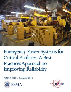
FEMA 2014
FEMA P-1019, Emergency Power Systems for Critical Facilities: A Best Practices Approach to Improving Reliability (September 2014)
At critical-facility data centers, place generators, ATS, fuel tanks and pumps above the greatest of BFE + 3 ft, DFE + 1 ft and 500-year elevation + 1 ft, and prefer elevation to dry floodproofing.
- Generators over 300 kW are almost exclusively diesel-fueled.
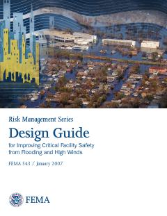
FEMA 2007
FEMA 543, Design Guide for Improving Critical Facility Safety from Flooding and High Winds (Risk Management Series, January 2007)
For site selection, look beyond the 100-year flood to the 500-year (0.2%) flood and the facility's occupancy category, and avoid flood hazard areas where possible.
- A freeboard of 1 to 3 feet above the flood elevation is often applied to critical facilities.