
TM 5-698-4 Failure Modes, Effects and Criticality Analyses (FMECA) for Command, Control, Communications, Computer, Intelligence, Surveillance, and Reconnaissance (C4ISR) Facilities (29 September 2006)
U.S. Army Corps of Engineers (Headquarters, Department of the Army) · Headquarters, Department of the Army
An Army manual on performing FMEA and FMECA for critical facility systems such as power, generators and HVAC. It includes ready-made worksheets, severity and occurrence ranking tables, quantitative criticality and RPN methods, and how to account for redundancy.
U.S. public domain — U.S. Government work; free to reuse
On this page
Overview
TM 5-698-4 guides facility managers through Failure Mode, Effects and Criticality Analysis (FMECA) for a C4ISR facility. Because these facilities include several redundant systems to achieve very high availability, the manual provides an easy evaluation method for the effect of redundancy on failure rates and probability of occurrence. The examples use HVAC systems but the process applies to any electrical or mechanical system. FMECA consists of two analyses: the FMEA, which examines failure modes and their effects on the system, and the criticality analysis (CA), which prioritises them by failure rate and severity of effect.
The text records that FMECA originated with NASA to verify space hardware reliability, that the cancelled MIL-STD-785B Task 204 and MIL-STD-1629A set the procedures, and that the concepts should be applied to all critical systems. The FMECA should start as soon as preliminary design information exists and remain a living document updated during use. Stated benefits include highlighting single-point failures, helping develop test and troubleshooting methods, and providing a foundation for reliability, maintainability, safety and logistics analyses.
Chapter 3 covers FMEA steps: define the system (functional or hardware approach), ground rules, block diagrams, failure mode identification, effects analysis, detection methods, compensating provisions and a 1-to-10 severity ranking. Chapter 4 computes criticality in two ways: quantitative when data exist (alpha failure mode ratio, beta effect probability, failure rate and mission time) and qualitative when they do not (Risk Priority Number, the product of occurrence, severity and optionally detection rankings). The effect of redundancy is treated separately for both.
Chapter 5 covers criticality ranking and the criticality matrix. The matrix can separate components with equal RPN but different severity and occurrence: a component with severity 3 and occurrence 10 and one with severity 10 and occurrence 3 both score an RPN of 30, yet the severity-10 item should be handled first. The manual dates from 2006 but the methodology remains standard practice. Appendix B lists failure mode distribution sources while the Army worksheets (DA Forms 7610 to 7614) appear as figure examples.
Key points
- Severity is ranked from 1 (no effect) to 10 (safety, health or environmental hazard occurring without warning); a ranking of 8 means all of the mission is lost with a significant delay in restoring function.
- In the alternative category scheme Category I is Minor, II Marginal and III Critical (severe injury or major system damage); this scheme is not used for qualitative analysis because severity and occurrence need equal scales.
- Failure mode ratios (alpha) for an item must sum to 1. Example for an air handler: 0.55 blows too little air, 0.05 too much and 0.40 no air. Failure rates are expressed per 10^6 hours.
- Failure mode criticality is Cm = beta x alpha x lambda_p x t, where lambda_p is the item failure rate and t the mission-phase duration.
- Worked example: an item with a failure rate of 12.058 failures per million hours (NPRD-95), split 0.29 no output and 0.71 degraded, has an item criticality Cr of 12.058 for t = 1 h.
- Occurrence rankings map to failure rates from 1 = 1/10,000 (remote) through 5 = 1/500 (moderate) to 10 = 1/10 or more (almost certain).
- The Risk Priority Number is Severity (1-10) x Occurrence (1-10), optionally multiplied by Detection: RPN = S x O x D.
- Redundancy adjusts the occurrence ranking qualitatively by O' = O x M/(N-1), where M components are needed out of N installed; with only one spare O is unchanged, so lowering occurrence needs at least two extra components. Example: RPN drops from 9 x 8 = 72 to 6 x 5 = 30.
- A component-level FMEA gives high severity because there is no redundancy at that level; at system level severity may fall when a backup is in place.
- The criticality matrix separates items with equal RPN; failures in the upper right (high occurrence, high severity) are evaluated first for redesign such as adding redundancy.
Using it in design
- At design stage run a functional FMEA of each critical system (power, generators, cooling); do not start without schematics, bill of materials, block diagram and the mission requirement.
- Where you have no data use the qualitative RPN method but keep severity and occurrence scales equal; for components with data compute quantitative criticality from alpha, beta, failure rate and mission time.
- Adjust for redundancy with O' = O x M/(N-1), remember that a single spare does not change the occurrence ranking, and record the effect of redundancy on RPN (such as 72 to 30) in the design rationale.
- Place results in a criticality matrix to separate failures with the same RPN but different severity, and give priority to severity-10 items.
- Keep the FMECA updated for the life of the facility and use it as the starting point for RCM, the maintenance plan and failure detection design.
- List single-point failures and flag them as redesign candidates (redundancy, monitoring); FMECA examines single failures, so multiple failures need fault tree analysis.
Monthly newsletter · free
Keep your reading list current
Once a month: new library sources, changes to Turkish regulations and upcoming data centre events.
SoSo CAD
Assess redundancy through scenarios
Compare normal operation and equipment failures in SoSo CAD, with supplied loads and capacity shortfalls in one view.
Request a demo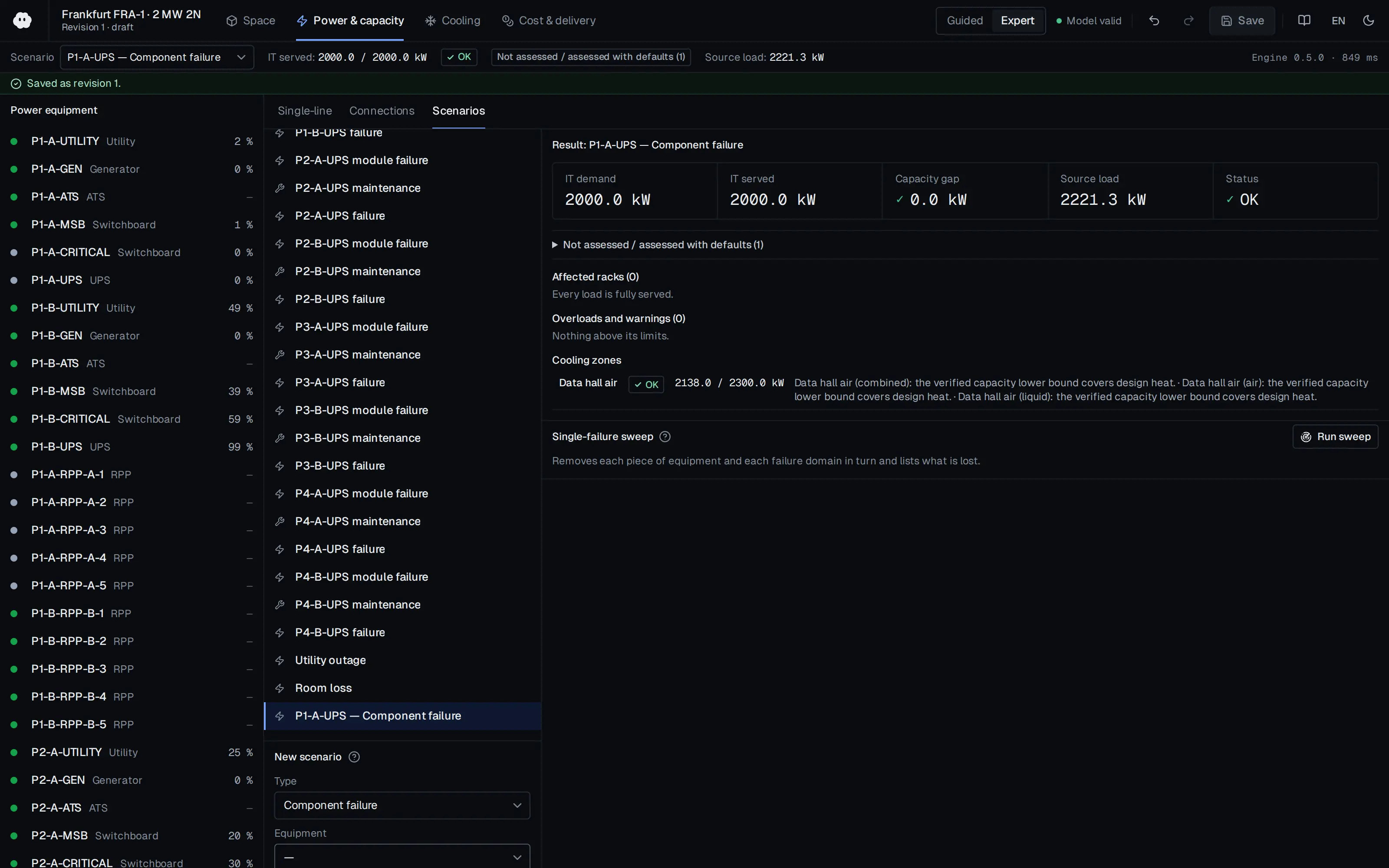
Who should read it
Reliability, electrical and mechanical engineers carrying out design-stage risk analysis of critical infrastructure.
Document contents
- Chapter 1 Introduction to FMECA: definition, history, benefits, team effort, characteristics
- Chapter 2 Preliminary Items Required: requirements, goals
- Chapter 3 FMEA Methodology Steps
- 3-2 Define the system to be analyzed (functional/hardware approach)
- 3-4 Block diagrams
- 3-5 Failure mode identification
- 3-6 Failure effects analysis
- 3-7 Failure detection methods / 3-8 Compensating provisions
- 3-9 Severity ranking
- Chapter 4 FMECA Methodology
- 4-4 Quantitative criticality analysis
- 4-5 Effects of redundancy: quantitative
- 4-6 Qualitative criticality analysis
- 4-7 Effects of redundancy: qualitative
- Chapter 5 Criticality Ranking: Quantitative and Qualitative; criticality matrix
- Chapter 6 Results of FMECA / Chapter 7 Conclusions
Read the document
usace-tm-5-698-4-fmeca.pdf
U.S. public domain — U.S. Government work; free to reuse
The document is provided unaltered because its licence permits redistribution.
Publication details
- Authors
- Headquarters, Department of the Army
- Publisher
- U.S. Army Corps of Engineers (Headquarters, Department of the Army)
- Year
- 2006
- Document language
- English
- Source type
- Government / public
- Access
- Open licence — downloadable
- Licence
- U.S. public domain — U.S. Government work; free to reuse
- Licence evidence
- www.copyright.gov
Original licence note
DoD/USACE criteria marked "Approved for public release; distribution unlimited"; work of the U.S. Government (17 U.S.C. 105).
Citation
Headquarters, Department of the Army (2006). TM 5-698-4 Failure Modes, Effects and Criticality Analyses (FMECA) for Command, Control, Communications, Computer, Intelligence, Surveillance, and Reconnaissance (C4ISR) Facilities (29 September 2006). U.S. Army Corps of Engineers (Headquarters, Department of the Army). https://www.wbdg.org/FFC/ARMYCOE/COETM/tm_5_698_4.pdf
Events on this subject
Browse the events calendarAll content and rights belong to the respective authors and publishers. SoSo CAD provides only the citation, its own summary and a link to the source, and is not responsible for the sources' content.
Related sources
All sources on this topic
U.S. Army Corps of Engineers (Headquarters, Department of the Army) 2002
TM 5-693 Uninterruptible Power Supply System Selection, Installation, and Maintenance for Command, Control, Communications, Computer, Intelligence, Surveillance, and Reconnaissance (C4ISR) Facilities (31 May 2002)
Calculate availability from MTBF and MTTR before choosing a UPS configuration; apply the same method to single-unit, N+1 and dual-redundant layouts to compare the gain from redundancy with the cost of the added components.
- C4ISR facilities require a reliability level of 99.9999 percent (the six-nine rule), which may call for greater redundancy.
Huawei Digital Power 2022
Data Center PowerPOD 3.0 Technology White Paper
Add a 'prefabricated power train' block type (transformer, LV, UPS, feeders) carrying footprint, weight and a clearance envelope.
- Average rack power rose from 4 kW to 6-8 kW and is heading to 12-16 kW.
Eaton 2016
Best Practices for Modernizing Vintage Data Centers
Add a designLifeYears catalog parameter per equipment type, default to the range midpoint, and drive a TCO/refresh timeline from it.
- Rack PDU 8-12 yr; power cables 8-20 yr; busway 8-20 yr
U.S. Army Corps of Engineers 2006
TM 5-698-2, Reliability-Centered Maintenance (RCM) for Command, Control, Communications, Computer, Intelligence, Surveillance, and Reconnaissance (C4ISR) Facilities (6 October 2006)
At design stage carry out an FMEA for each critical system and record failure modes, effects and detection methods as input to the RCM decision logic; the text stresses that RCM starts in design and continues for the life of the facility.
- For an exponential failure distribution with constant failure rate, an item with a 1000-hour MTBF has only a 37 percent probability of surviving 1000 hours of continuous operation.
Standards (MDPI AG) 2026
Arc-Flash Hazards: Standards Development Framework in Facilities of National Importance in Healthcare and Data Centers
Schedule the arc-flash study after the coordination study and make that order a mandatory step in the project plan and model.
- Example studies assumed available utility fault current of 21,000 A for the 440 V residential service and 21,000-40,000 A for the 480 V/1200 A commercial service.

Open Compute Project Foundation 2022
Leak Detection and Intervention, Revision 1.0 (OCP Advanced Cooling Solutions white paper)
Run a probability-and-impact leak risk analysis at project start, specify BSPP/O-ring joints for serviceable connections and check the O-ring compound against the coolant chemistry using the full wetted-materials list.
- A UQD2 dry-break quick disconnect is specified to drip less than 0.063 cc when disconnected at 200 psi.