
Paralleling Generator Set Systems and Design
Caterpillar · Don Dentino
Caterpillar LEXE1365-01 (Don Dentino, 2018) compares three generic strategies for paralleling generator sets: controls mounted on each set, stand-alone paralleling controls, and fully integrated paralleling switchgear.
On this page
Overview
For each strategy the paper sets out functions, typical applications, advantages and drawbacks across cost, flexibility, redundancy, factory testing and site-integration burden. On-set controls are positioned as low-cost for simple LV island systems, controls-only for MV/HV and retrofits, and integrated switchgear as the most flexible and redundant choice for complex or utility-paralleled systems.
On-generator controls provide dead-bus arbitration, auto and manual synchronising, kW and kVAR sharing, load shed and add, and optional load-demand set cycling. They are typically limited to low voltage (under 600 V); MV uses remote controls-only arrangements. The connecting switching device needs about a 5-cycle close and open time to avoid out-of-phase paralleling, and without master controls these systems are mostly limited to an isolated common bus or a single generator to utility.
Controls-only solutions typically lack utility-grade protective relays and must be wired to the distribution switchgear on site. Integrated paralleling switchgear allows redundant PLCs, networks and relays, factory integration testing and metal-clad, arc-resistant construction, at higher cost.
Key points
- Three strategies: on-set controls, controls-only panels or PLCs, integrated paralleling switchgear.
- On-set paralleling is typically limited to under 600 V; MV needs remote controls-only arrangements.
- The connecting device needs about 5-cycle close/open speed to avoid out-of-phase paralleling.
- Without master controls, on-set systems are mostly limited to an isolated common bus or one generator to utility.
- Controls-only solutions lack utility-grade protective relays and need site interconnection to distribution switchgear.
- Integrated switchgear offers redundant PLCs, networks and relays, factory integration testing and arc-resistant construction.
Using it in design
- Build an architecture selector with the three options and show consequences: LV-only limit for on-set, required breaker closing speed, and master-controller need for complex sequences.
- For MV generator plants or utility-paralleled designs, default to controls-only or integrated switchgear.
- For Tier IV or other high-redundancy designs, prompt for redundant PLCs and protective relaying.
Monthly newsletter · free
Keep your reading list current
Once a month: new library sources, changes to Turkish regulations and upcoming data centre events.
SoSo CAD
Review your power design in SoSo CAD
Inspect supply paths, equipment loads and UPS failure scenarios in one model.
Request a demo
Who should read it
Electrical designers choosing a paralleling architecture and specifiers of paralleling switchgear.
Related standards
- NFPA 110
- UL 1558
- IEEE C37.20.2
Publication details
- Authors
- Don Dentino
- Publisher
- Caterpillar
- Year
- 2018
- Document number
- LEXE1365-01
- Document language
- English
- Source type
- Manufacturer
- Access
- Free to read
- Licence
- Copyright retained; citation only — the publisher’s terms apply to the original document
Citation
Don Dentino (2018). Paralleling Generator Set Systems and Design. Caterpillar. LEXE1365-01. https://www.finning.com/content/dam/finning/en_gb/Documents/Industries/ElectricPower/cat-white-papers-march-2024/Paralleling%20Generator%20Set%20Systems%20And%20Design%20(LEXE1365-01).pdf
Events on this subject
- Electricity Eurasia 2027
- ELECO 2026 Elektrik-Elektronik ve Biyomedikal Mühendisliği Konferansı
- ICCI 2027 – Uluslararası Enerji ve Çevre Fuarı ve Konferansı
All content and rights belong to the respective authors and publishers. SoSo CAD provides only the citation, its own summary and a link to the source, and is not responsible for the sources' content.
Related sources
All sources on this topicCaterpillar 2014
Demystifying Generator Set Ratings
Store per rating the kW, average-load-factor limit, annual-hour limit, overload allowance and a utility-paralleling-permitted flag.
- ESP: 200 h/year maximum, 24-hour average at most 70% of ESP.
Open Compute Project Foundation 2026
Clean Backup Power Technology Requirements, Base Specification Version 0.3 (effective Apr 22, 2026)
Extend the generator catalogue with technology type (diesel, HVO, gas, H2 ICE, PEM fuel cell), emissions factor relative to the 1742 lb/MWh baseline, start time, block-load capability and NFPA 110 level.
- Overload 110% for 60 s and 150% for 3 s; transient voltage response to ISO 8528-5 G3; steady-state frequency within +/-0.5%.
Energies (MDPI AG) 2023
Reliability Assessment of the Configuration of Dynamic Uninterruptible Power Sources: A Case of Data Centers
When choosing among DRUPS or UPS configurations, first screen with the graph-based method to identify the best candidates, then do the detailed RBD calculation for that candidate only.
- Single system: λ = 3.10 × 10^-6 1/h, A = 0.999949, MTBF 306,600 h (35 years).
U.S. DoD (UFC) 2023
UFC 3-540-01 Engine-Driven Generator Systems for Prime and Standby Power Applications (1 August 2014, Change 3, 26 January 2023)
Include transient and steady-state loads, transformer inrush, motor starting and UPS load in the generator sizing study, and calculate UPS charging load using the minimum charging current allowed while on generator.
- Harmonic analysis is required when switching power supplies make up 25% or more of the system load.
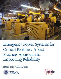
FEMA 2014
FEMA P-1019, Emergency Power Systems for Critical Facilities: A Best Practices Approach to Improving Reliability (September 2014)
At critical-facility data centers, place generators, ATS, fuel tanks and pumps above the greatest of BFE + 3 ft, DFE + 1 ft and 500-year elevation + 1 ft, and prefer elevation to dry floodproofing.
- Generators over 300 kW are almost exclusively diesel-fueled.
FEMA 2007
FEMA 543, Design Guide for Improving Critical Facility Safety from Flooding and High Winds (Risk Management Series, January 2007)
For site selection, look beyond the 100-year flood to the 500-year (0.2%) flood and the facility's occupancy category, and avoid flood hazard areas where possible.
- A freeboard of 1 to 3 feet above the flood elevation is often applied to critical facilities.