
Clean Backup Power Technology Requirements, Base Specification Version 0.3 (effective Apr 22, 2026)
Open Compute Project Foundation
A draft from the OCP DCF Sustainability project, authored by Google and Microsoft, that sets measurable requirements for zero-carbon and low-carbon-transition technologies meant to replace diesel standby generators. It does not prescribe a technology; it uses performance criteria to decide what is acceptable for critical load.
OWFa 0.9 — Open Compute open specification licence; redistribution permitted
On this page
Overview
The specification is performance-based and technology-agnostic. Candidate solutions include PEM fuel cells, clean-fuelled generators (renewable natural gas, e-fuels, hydrogen, green methanol) and long-duration energy storage, and the document gives them one common set of criteria for judging whether they can serve as mission-critical backup. The aim is to give suppliers a clear target and to align the industry, colocation providers included, on the same requirements.
'Clean' has two tiers. Zero-carbon means no Scope 1 emissions of CO2, NOx, SOx or PM at the point of use in steady-state operation. Low-carbon transition means considerably lower Scope 1 emissions than a Tier 2 diesel generator without after-treatment. The comparison baseline is a diesel engine emitting 1742 lb/MWh of CO2. Emissions rank from highest to lowest as diesel, diesel with SCR, natural gas, natural gas with SCR, hydrogen engines, and PEM fuel cells, which approach zero. The text names reducing the baseline to under ten percent as the ideal target.
Technical requirements sit in four tables. The system must be a self-contained grid-forming source that can isolate from the utility, deliver power within 10 s of the signal and transfer to island mode in under 8 ms. The target scale is 40-50 MW sites growing to 300 MW-1 GW, with a preferred module size of 2-10 MW. Typical availability is 99.99% for the backup system and 99.999% at site level through N+m. The testing section covers factory acceptance, a sub-scale efficiency validation and site acceptance tests.
Energy storage such as BESS is deliberately placed in a separate category. Generation units can run indefinitely if refuelled, whereas storage may only be used where the grid operator guarantees that an outage will never exceed its duration. Several values remain as placeholders in square brackets ([X] MW continuous output, [X] kg CO2e per kW embodied-carbon cap), and the version history shows only an initial version, so the document is clearly a draft.
Key points
- The emissions baseline is a diesel engine at 1742 lb CO2/MWh; ranking runs diesel, diesel+SCR, natural gas, natural gas+SCR, hydrogen engines, PEM fuel cells (near zero).
- Self-contained grid-forming source; start-up within 10 s of signal; island transfer under 8 ms (quarter cycle); 100% block load acceptance.
- Overload 110% for 60 s and 150% for 3 s; transient voltage response to ISO 8528-5 G3; steady-state frequency within +/-0.5%.
- THD at most 5% at full load (IEEE 519); IEEE 2800 ride-through and IEEE 1547-2018 certification; output 480 VAC 3-phase 60 Hz (performance guaranteed at 13.8 kV) or 0-800 VDC.
- Scale 40-50 MW rising to 300 MW-1 GW; module 2-10 MW; TRL 8 or above; backup availability 99.99% and 99.999% site level with N+m; concurrent maintainability.
- Indefinite runtime with integral fuel storage sized for refuelling time; containerised or skid, typically 2.5 x 6.0 m and under 12,000 kg; -20 to +50 C; NFPA 110 Level 1; explosion-proof enclosures for hydrogen or e-gas.
- Zero-carbon goal is 0.0 g/kWh direct CO2e and zero criteria pollutants; low-carbon transition must meet EPA Tier IV; hydrogen engines NOx under 0.02 g/bhp-hr with SCR; third-party verified Type III EPD per ISO 14025.
- Noise limited to 75 dBA at 1 m from the enclosure; chemical storage must recover over 95% of critical minerals (lithium, cobalt, nickel); lead, cadmium, mercury and hexavalent chromium are prohibited.
- System life of at least 15 years with midlife refurbishment and spare parts for at least 10 years after end of life; interface must natively support DNP3 or IEC 61850 and OpenADR 2.0b.
Using it in design
- Extend the generator catalogue with technology type (diesel, HVO, gas, H2 ICE, PEM fuel cell), emissions factor relative to the 1742 lb/MWh baseline, start time, block-load capability and NFPA 110 level.
- In the backup-power check, verify start-up within 10 s and 100% block load; where a source cannot meet them, require a UPS or battery bridge sized for the gap.
- For hydrogen or e-gas options, add rules for explosion-proof enclosures, hazardous-area classification and on-site fuel storage sized to the refuelling time.
- Restrict storage-only backup to cases where the grid operator guarantees a maximum outage duration; otherwise flag that a generation unit is needed.
- Report Scope 1 backup emissions and equipment embodied carbon (Scope 3, from the EPD) in the sustainability summary.
- Carry the module footprint (2.5 x 6.0 m, under 12,000 kg) and the 75 dBA at 1 m limit into layout and noise checks.
Monthly newsletter · free
Keep your reading list current
Once a month: new library sources, changes to Turkish regulations and upcoming data centre events.
SoSo CAD
Review your power design in SoSo CAD
Inspect supply paths, equipment loads and UPS failure scenarios in one model.
Request a demo
Who should read it
Electrical designers, sustainability engineers and equipment suppliers weighing backup-power architecture, generator alternatives and carbon targets together.
Document contents
- License
- Compliance with OCP Tenets
- Overview
- Introduction to clean backup technologies
- Technology Agnosticism and Focus
- Definition of Clean
- Technology Evaluation Methodology and Baseline
- Emissions Reduction Methodology and Technology Eligibility
- Definitions
- Referenced Codes and Standards
- Detailed Specifications
- Technical Viability and Reliability
- Scope, Scale, Reliability and Operating Environment
- Sustainability and Emissions Requirements
- Testing, Management, and Lifecycle
- Site Acceptance Testing (SAT)
- Compliance
Related standards
- ISO 8528-5
- NFPA 110
- NFPA 2
- IEEE 1547-2018
- IEEE 2800
- IEEE 519
- UL 2200
- UL 9540
- IEC 62282-2
Read the document
ocp-clean-backup-power-spec.pdf
OWFa 0.9 — Open Compute open specification licence; redistribution permitted
The document is provided unaltered because its licence permits redistribution.
Publication details
- Authors
- Open Compute Project Foundation
- Publisher
- Open Compute Project Foundation
- Year
- 2026
- Document number
- v0.3
- Document language
- English
- Source type
- Industry body
- Access
- Open licence — downloadable
- Licence
- OWFa 0.9 — Open Compute open specification licence; redistribution permitted
- Licence evidence
- www.opencompute.org
Original licence note
Page 4 states contribution under the Modified Open Web Foundation Agreement 0.9 (OWFa 0.9) and use under the Modified OWFa 0.9 Final Specification Agreement.
Citation
Open Compute Project Foundation (2026). Clean Backup Power Technology Requirements, Base Specification Version 0.3 (effective Apr 22, 2026). Open Compute Project Foundation. v0.3. https://www.opencompute.org/documents/ocp-base-specification-clean-backup-power-technology-requirements-v0-3-pdf/
Events on this subject
- Electricity Eurasia 2027
- ICCI 2027 – Uluslararası Enerji ve Çevre Fuarı ve Konferansı
- The smarter E Europe (Intersolar Europe, ees Europe, Power2Drive, EM-Power)
All content and rights belong to the respective authors and publishers. SoSo CAD provides only the citation, its own summary and a link to the source, and is not responsible for the sources' content.
Related sources
All sources on this topic
Open Compute Project Foundation 2026
White Paper: Requirements for Energy Storage Systems Used in Data Centers, Revision 1.0, Version 1.0 (OCP Ready Facilities, January 2026)
Fix the ESS architecture (DC or AC coupled, distributed or centralised, backup-only or grid-interactive), write the applicable NFPA 70, NFPA 855 and IEC 62933 parts into the design basis, and consult the authority having jurisdiction (AHJ) early.
- FM Global DS 5-33 (as cited) recommends battery installations in rooms with at least a 2-hour fire rating.
WSEAS TRANSACTIONS ON POWER SYSTEMS (World Scientific and Engineering Academy and Society (WSEAS)) 2026
Design and Prototype of a Microgrid for Enhancing Reliability of Power Supply for Artificial Intelligence Data Centers
Follow the energy-balance chain in a PV/BESS sizing helper (daily load split, conversion losses, usable depth of discharge, power rating against night peak); report usable-energy duration rather than nameplate duration and make DoD an explicit input.
- Covering 60% of demand needs 81,857 kWh/day from PV after 5% DC-AC and 10% battery losses.
arXiv preprint (Texas Tech University / PNNL; submitted to Renewable and Sustainable Energy Reviews) 2026
A Critical Review of Grid Integration Challenges and Flexibility Opportunities for Large-Scale Data Centers
Base interconnection studies on staged, updatable facility data rather than a single static MW value; requested peak MW and annual energy alone do not establish integration.
- Under IEEE 519-2022, voltage-distortion limits at the PCC are the system owner's responsibility and current-distortion limits are the user's; a scalar THD cannot rule out narrow-band resonance.
Energies (MDPI AG) 2023
Reliability Assessment of the Configuration of Dynamic Uninterruptible Power Sources: A Case of Data Centers
When choosing among DRUPS or UPS configurations, first screen with the graph-based method to identify the best candidates, then do the detailed RBD calculation for that candidate only.
- Single system: λ = 3.10 × 10^-6 1/h, A = 0.999949, MTBF 306,600 h (35 years).
U.S. DoD (UFC) 2023
UFC 3-540-01 Engine-Driven Generator Systems for Prime and Standby Power Applications (1 August 2014, Change 3, 26 January 2023)
Include transient and steady-state loads, transformer inrush, motor starting and UPS load in the generator sizing study, and calculate UPS charging load using the minimum charging current allowed while on generator.
- Harmonic analysis is required when switching power supplies make up 25% or more of the system load.
FEMA 2014
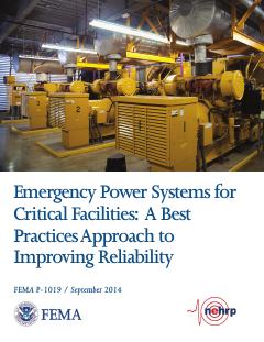
FEMA P-1019, Emergency Power Systems for Critical Facilities: A Best Practices Approach to Improving Reliability (September 2014)
At critical-facility data centers, place generators, ATS, fuel tanks and pumps above the greatest of BFE + 3 ft, DFE + 1 ft and 500-year elevation + 1 ft, and prefer elevation to dry floodproofing.
- Generators over 300 kW are almost exclusively diesel-fueled.