
Data Center Projects: Establishing a Floor Plan
Schneider Electric · Neil Rasmussen, Wendy Torell
Schneider Electric WP 144 gives structured rules for laying out data-hall room boundaries and IT rows; the floor plan should be fixed after the system concept but before detailed design.
On this page
Overview
The reasoning is that density, phasing and criticality are specified per row, so the floor plan has to be settled before detailed design. Rows are laid out as hot-aisle/cold-aisle pairs on a 2 ft (600 mm) tile grid. As a rough estimate, rack locations equal room area divided by 28 sq ft (2.6 m2) per rack. Four standard pitches, measured mid-cold-aisle to mid-cold-aisle, are defined: A compact 7 tiles/14 ft (4 ft cold, 3 ft hot); B wide cold aisle 16 ft (6 ft cold, 3 ft hot); C wide hot aisle 16 ft (4 ft cold, 5 ft hot); D wide hot and cold 18 ft (6 ft cold, 5 ft hot).
Pitch B provides 50% more raised-floor cooling capacity in the cold aisle for higher-density raised-floor designs; pitches C and D suit racks with rear cooling accessories. On hard floors the pitch can be compressed provided aisles stay at least 3 ft (hot) and 4 ft (cold); 50 in deep racks, for example, give a minimum pitch of 15 ft 4 in. Row ends need at least 2 tiles of clearance to plain walls (3 preferred in large rooms), rows over 10 racks may need breaks by local regulation, and rows of 1-3 racks should be avoided.
The paper shows how columns and partitions can remove whole rows. In a 40-rack-location room with no column, a column in an aisle that forces rows to shift drops the count to 29, a loss of over 25%, while rotating the layout axis 90 degrees keeps 35. A misplaced partition lost 10 of 80 racks (12%). Typical losses from unplanned layouts are 10-20% of total rack locations and 20% or more of power density capability.
Hot-aisle/cold-aisle layout allows a power density increase of up to 100% or more versus random or same-direction layouts, and a poor layout can cut permissible rack power by over 50% with certain cooling architectures. The step-by-step planning sequence covers constraints, layout axis selection, row-end clearances, density zoning and raised-floor index points, and closes with common errors observed in existing facilities.
Key points
- Rack-location estimate: room area / 28 sq ft (2.6 m2) per rack.
- Four pitches: A 14 ft (4 ft cold/3 ft hot), B 16 ft (6/3), C 16 ft (4/5), D 18 ft (6/5).
- Pitch B gives 50% more raised-floor cooling capacity in the cold aisle; C and D suit racks with rear cooling accessories.
- Hard-floor pitch can be compressed if aisles stay at least 3 ft (hot) and 4 ft (cold); 50 in racks give a 15 ft 4 in minimum.
- 40-rack example: a column in an aisle drops it to 29 (over 25% loss); rotating the axis 90 degrees keeps 35.
- Hot/cold aisle layout allows 100% or more density increase versus random layouts; a poor layout can cut permissible rack power by over 50%.
- Row ends need at least 2 tiles to plain walls (3 preferred in large rooms); rows over 10 may need breaks; avoid rows of 1-3 racks.
- Unplanned layouts typically lose 10-20% of rack locations and 20% or more of density capability; a misplaced partition lost 10 of 80 racks.
Using it in design
- Run the layout engine on a 600 mm / 2 ft grid with row-pair pitch presets A-D (14/16/16/18 ft), auto-selected from raised-floor, rear-door accessory, containment and density inputs.
- Rule checks: minimum cold aisle 4 ft, hot aisle 3 ft, row-end clearance at least 2 tiles; flag rows of 1-3 racks, rows over 10 racks without a break, columns inside aisles, rows facing hot-to-cold, perpendicular rows and odd numbers of rows.
- Run both layout axes automatically and report rack count per axis.
- Require surveyed column dimensions and a raised-floor index point tied to the row layout; use racks = area / 2.6 m2 as a quick estimate before detailed layout.
Monthly newsletter · free
Keep your reading list current
Once a month: new library sources, changes to Turkish regulations and upcoming data centre events.
SoSo CAD
Check cooling capacity alongside your design
Review zone heat loads, available capacity and the capacity balance after the largest unit is lost in SoSo CAD.
Request a demo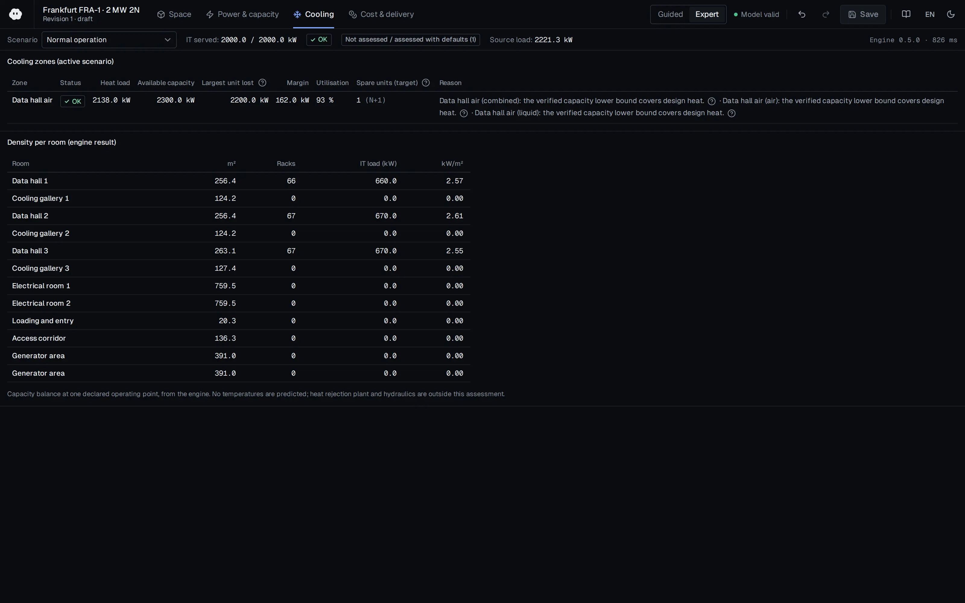
Who should read it
Designers laying out data halls and operations engineers investigating capacity lost in an existing facility.
Related standards
- ASHRAE TC9.9 Thermal Guidelines
- ANSI/TIA-942
Publication details
- Authors
- Neil Rasmussen; Wendy Torell
- Publisher
- Schneider Electric
- Year
- 2015
- Document number
- WP 144
- Document language
- English
- Source type
- Manufacturer
- Access
- Free to read
- Licence
- Copyright retained; citation only — the publisher’s terms apply to the original document
Citation
Neil Rasmussen; Wendy Torell (2015). Data Center Projects: Establishing a Floor Plan. Schneider Electric. WP 144. https://download.schneider-electric.com/files?p_Doc_Ref=SPD_VAVR-6KYMZ7_EN
Events on this subject
Browse the events calendarAll content and rights belong to the respective authors and publishers. SoSo CAD provides only the citation, its own summary and a link to the source, and is not responsible for the sources' content.
Related sources
All sources on this topic
Open Compute Project Foundation 2020
Colocation Facility Guidelines for Deployment of Open Racks, Revision 4.0 (15 December 2020)
Check the delivery route against rack height plus 0.5 m, door and corridor widths, and the lift capacity, before agreeing to host or design for Open Racks.
- Maximum rack density is at least 8 kW (Acceptable) or 12 kW (Optimum); cold aisle width is at least 1,200 mm or 1,500 mm.
Schneider Electric 2020
Three Types of Edge Computing Environments and their Impact on Physical Infrastructure Selection
Add an environmentClass (it_space, commercial_office, industrial_harsh) plus indoor/outdoor flag that drives defaults and checks.
- IK01 = 0.14 J, IK05 = 0.7 J, IK10 = 20 J.
Schneider Electric 2020
Practical Guide to Preparing Edge Sites and Installing Micro Data Centers
In the edge template, allow a ventilated enclosure when IT load is 4 kW or less.
- In-rack mounted cooling units cover about 3.5 kW.
Schneider Electric 2020
The Different Types of Air Distribution for IT Environments
Model each white-space zone with supplyMode and returnMode enums (flooded, targeted, contained).
- Flooded supply/flooded return cools up to 3 kW per rack and suits small LAN rooms under 40 kW.
Schneider Electric 2017
Types of Prefabricated Modular Data Centers
Give the module catalog functional block, form factor, indoor/outdoor rating, walk-in flag, shipping sections, footprint and height.
- ISO containers are 20 x 8 ft and 40 x 8 ft, 8 ft 6 in or 9 ft 6 in high-cube.
Schneider Electric 2017
The Use of Ceiling-Ducted Air Containment in Data Centers
Add passive and active ducted racks and ducted HACS to the containment selector, with density limits tied to a ceiling plenum vacuum input (default 0.03 inH2O / 7.5 Pa, warning above 0.06 inH2O / 15 Pa).
- Cooling-to-IT airflow ratio: 1 for HACS, 1.2 or higher for ducted racks.