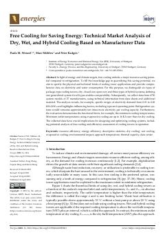
Check free-cooling feasibility from the required coolant outlet temperature, the tower approach (dry 10 K, open wet 5 K, closed wet 6.5 K) and the at-least-5 K coolant range.
Minimum outlet temperatures with evaporative cooling are up to 16 K lower than with dry cooling.
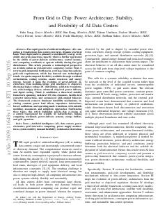
For large sites, capture grid-code inputs per jurisdiction (FRT curve, MW/min ramp limit, power-quality limits) as project inputs and flag UPS settings that transfer to battery or generator on shallow sags.
NVIDIA reports that 800 V DC instead of 415 V AC cuts copper requirements by 45%.
For large or AI facilities, record the UPS's fault ride-through behaviour (momentary cessation versus ride-through with minimum grid draw), the inverter current limit and the post-fault ramp rate, alongside the point-of-interconnection short-circuit ratio.
Unserved IT energy was 0.00000 MWh with the proposed controller versus 0.00208 MWh for a momentary-cessation benchmark.
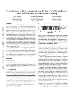
For an AI inference facility, set interconnection capacity from traces generated from the workload, not nameplate TDP or mean power; TDP sizing gave 1.19 MW against 0.75 MW trace-based (about 60% too much).
Generated facility traces show a peak-to-average ratio of 1.19, a load factor of 0.84 and a maximum 15-minute ramp of 0.11 MW.
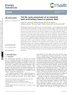
For UPS duty with a few cycles a year and minutes of autonomy, compare battery chemistries by environmental impact categories (GWP, ecotoxicity, resource depletion) as well as energy density, because production and EOL dominate.
Data centres account for about 37% of the roughly 3.4 billion USD global stationary-battery market, followed by telecom at 25%.
Give CRAC and condenser catalogue entries cooling kW, airflow (m3/min), electrical input kW, footprint, weight and service connections (refrigerant line sizes, condensate drain, humidifier water).
The 50 kW CRAC needs two ~25 mm refrigerant lines, a 22.2 mm condensate drain and a 6.4 mm humidifier water line.
Model a project as plan -> design -> build -> operate/assess and gate site selection behind the six completed requirements, warning if a site is chosen before they are set.
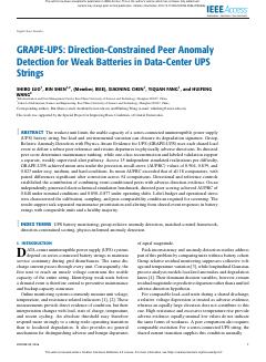
Require block-level (per-unit) voltage and resistance monitoring in UPS battery monitoring rather than string totals, citing that one weak unit in a series string limits the whole string's capacity.
On an independent electrochemical simulation benchmark, directed peer scoring achieved AUPRC 0.848 under nominal conditions and 0.850-0.877 under operating shifts.
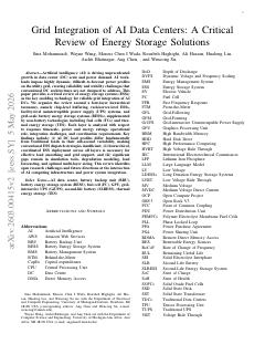
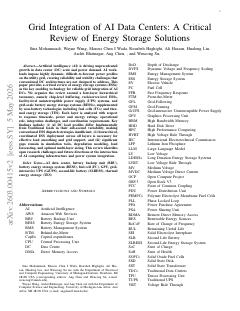
Layer storage by timescale (chip/server sub-ms to ms, rack ms to seconds, UPS and GiUPS sub-second to 10 s, BESS minutes to hours) and show each layer's duty in the coordination scheme.
Rapid AI load variations often induce 5-10% voltage swings within milliseconds.
Layer storage by timescale: GPU/server supercapacitors for sub-second swings, rack BBUs for minutes, facility GiUPS and BESS for grid services and longer durations; show each layer's duty and coordination separately in the architecture.
BESS cost fell from about $7,500/kWh in 1991 to $133/kWh in 2024, with about $80/kWh projected by 2030.
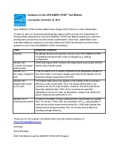
When ingesting vendor UPS efficiency figures, record the input configuration (three-phase) and whether the values follow ENERGY STAR or IEC 62040-3 methods.
DOE data show durations over 15 minutes do not change average efficiency.
Add EPD/PEP fields to each catalogue product: programme operator, PCR/PSR version, validity date, functional unit, reference product weight and rating, per-stage kg CO2e, emission factor used and exclusions such as batteries.
Standards allow a +/-5% margin of error on reported values, so indicators within 10% of each other should be treated as equal.
Place standard tap-off points with isolation valves, vent/drain/flush connections and strainers at every rack or CDU connection in liquid cooling layouts, sized from Q = flow x delta T x cp so future kW per position is explicit.
Keeping FWS liquid above dew point avoids condensation; the ASHRAE recommended dew point limit for air-cooled classes A1-A4 is 15 C.
Generate a TCS pre-commissioning test script from the piping model: proof pressure at 1.3-1.5 x design working pressure, minimum flushing flow per pipe size at 3-5 ft/s, and sequential leg isolation.
Procedure water: conductivity at most 50 uS/cm, pH at least 6, total aerobic bacteria at most 1000 CFU/ml.
Apply refrigerant-specific rules to two-phase DLC designs in place of water-loop rules: GWP below 700, A1 safety class, and vapour/liquid line sizing with under 0.2 bar evaporator-to-condenser loss.
Minimal filtration is about 100 um; ambient during operation should stay within 5-35 C.
All content and rights belong to the respective authors and publishers. SoSo CAD provides only the citation, its own summary and a link to the source, and is not responsible for the sources' content.